Lull 6K Service Manual User Manual
Page 282
Boom and Transfer
6-32
Service Manual — Models 644B, 6K, 844C, 8K, 1044C, 10K
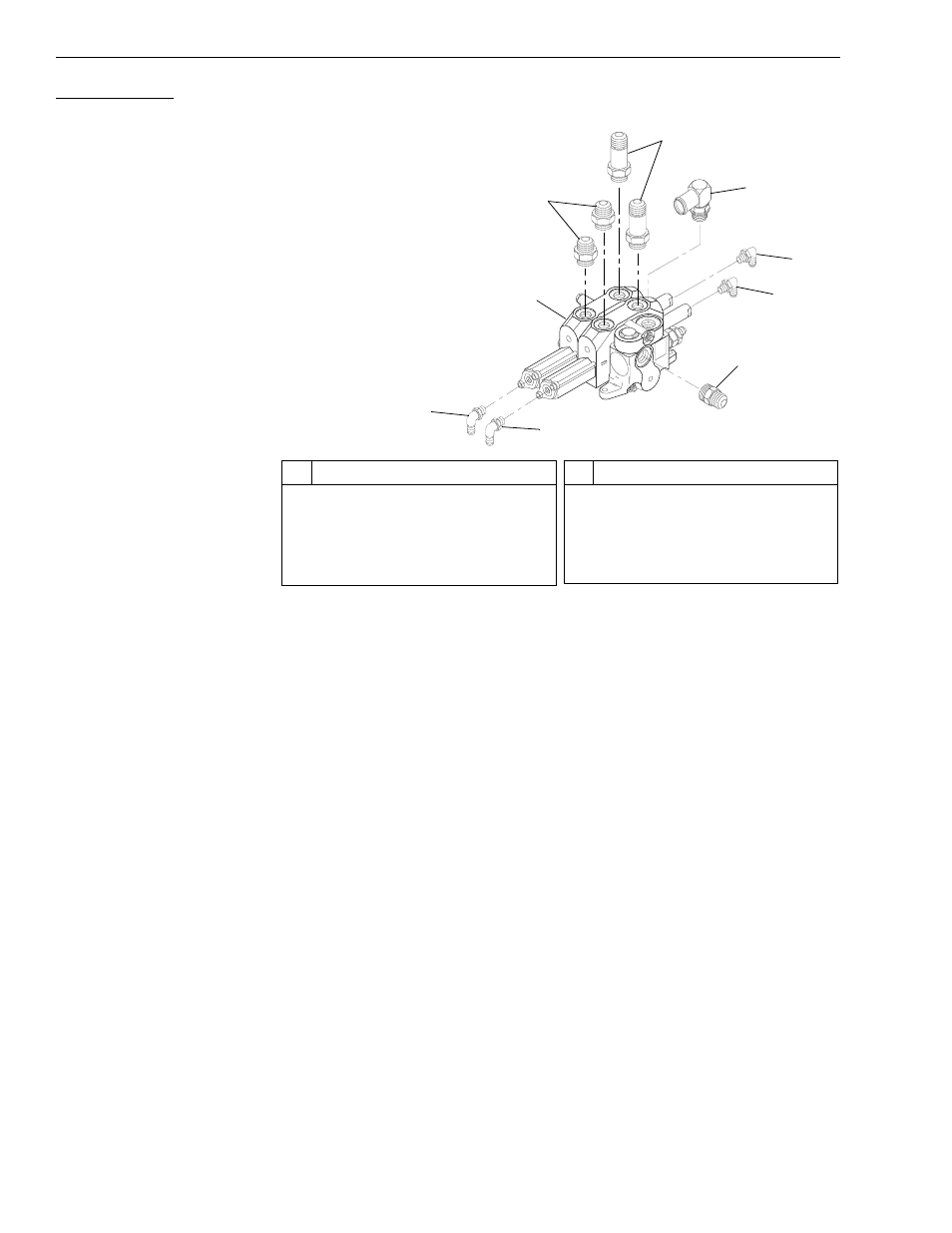
Fitting Removal
* This fitting is a tee on models with a pump unloader valve.
Fig. 6-19: Boom Control Valve Fittings
(Ref. Fig. 6-19) The following procedure describes removal of fittings on
the boom control valve.
1. Remove the four (4) elbows/tees (Items 5, 6, 8, and 9) from the boom
control valve assembly (Item 1).
2. Remove the hydraulic return hose elbow (Item 4).
3. Remove the two (2) short connectors (Item 2) and two long connectors
(Item 3) on the top of the boom control valve.
4. Remove the hydraulic tube connector (Item 7) on the side of the boom
control valve.
5. Clean all fittings with solvent and dry with compressed air. Inspect
fittings, including O-rings, for damage and replace if necessary.
#
Description
1
Boom Control Valve Assembly
2
Connector
3
Long Connector
4
Elbow (Hydraulic Return Hose)
5
Elbow*
#
Description
6
Elbow*
7
Connector (Hydraulic Tube)
8
Elbow*
9
Elbow
K1
1
1
0
1
2
3
4
6
7
9
8
5
6K-37 – S/N 101–317
6K-42 – S/N 101–119
644B-37 – S/N 101–590, 592–666
644B-42 – S/N 101–207
8K-42 – S/N 101–220
844C-42 – S/N 101–621
10K-42 – S/N 101–106
10K-54 – S/N 101–103
1044C-42 – S/N 101–116
1044C-54 – S/N 101–154