Lull 6K Service Manual User Manual
Page 353
Boom and Transfer
Service Manual — Models 644B, 6K, 844C, 8K, 1044C, 10K
6-103
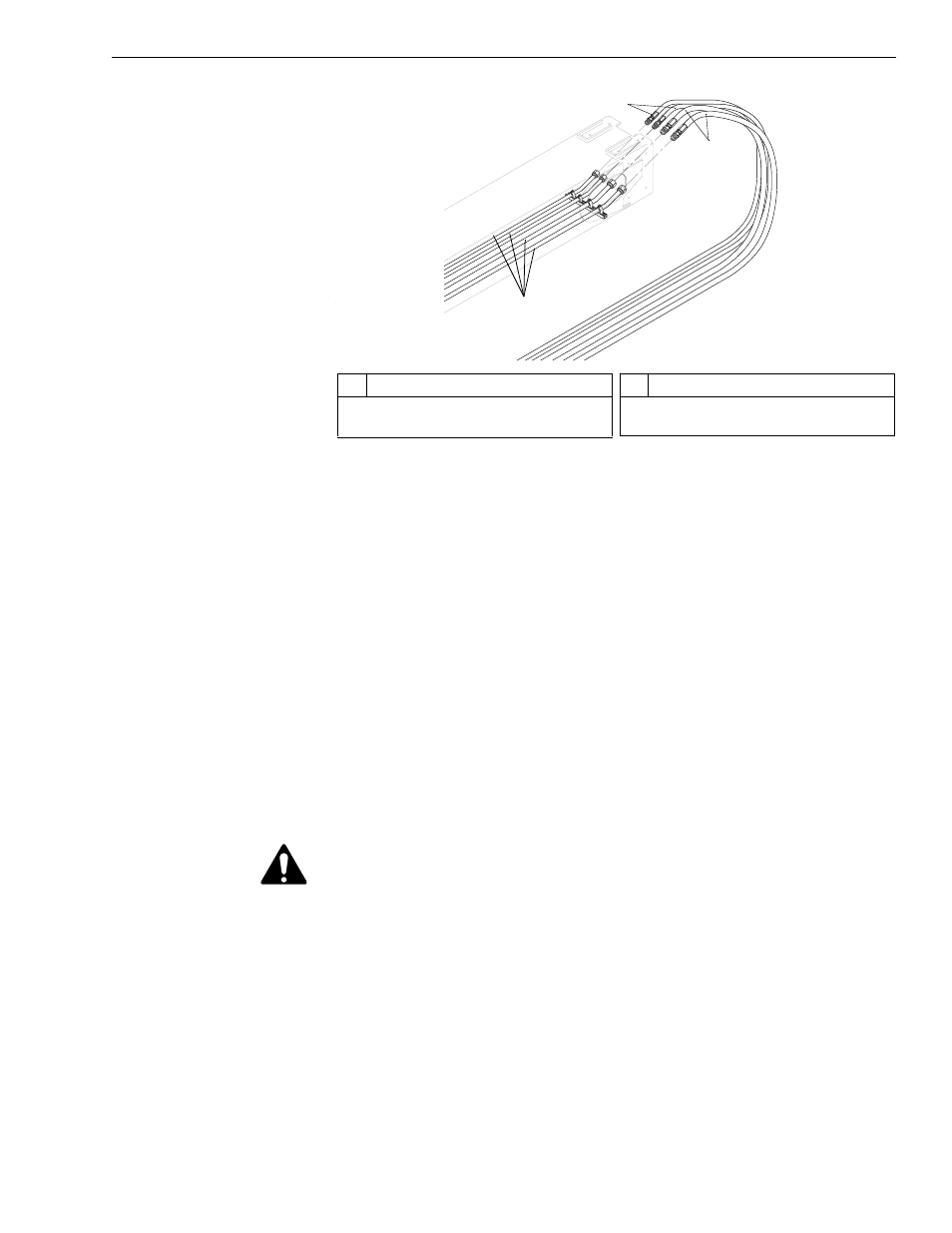
Fig. 6-107: Rear Hose Connections, Inner Boom
9. (Ref. Fig. 6-107) Tag and disconnect carriage tilt (Item 2) and auxiliary
hydraulic hoses (Item 1) from hydraulic tubes (Item 3) at rear of the
inner boom section. Cap hoses and tubes. Lay the hoses down at the
rear of the outer boom section.
Note: These hoses can be accessed through the service windows at the
rear of the inner, middle, and outer boom sections.
Note: “K” Model machines are not equipped with auxiliary hydraulics. For
these models, disregard procedures that refer to auxiliary
components. Some models are equipped with an additional set of
auxiliary hydraulics and will have two (2) additional sets of hoses,
tubes, and mounting hardware.
10. Start the engine and extend the middle boom out from the outer boom
section.
11. Support the middle boom section.
CAUTION: Make sure the crane, slings, chains, or other means of
support have sufficient capacity to support the weight of the
boom. The weight of the entire 3-section boom assembly is
approximately 5,400 pounds.
J
1
098
#
Description
1
Auxiliary Hydraulic Hoses
2
Carriage Tilt Hoses
#
Description
3
Hydraulic Tubes
1
2
3