Lull 6K Service Manual User Manual
Page 376
Boom and Transfer
6-126
Service Manual — Models 644B, 6K, 844C, 8K, 1044C, 10K
19. (Ref. Fig. 6-133) Position chain adjustment block (Item 3) tight against
back of anchor base (Item 2) as shown. Thread the chain adjustment
rod (Item 1) into the block until the specified measurement is obtained.
Push the adjustment rod fully into the anchor base.
20. With the outer boom still upside down, install the inclinometer. See
page 6-60.
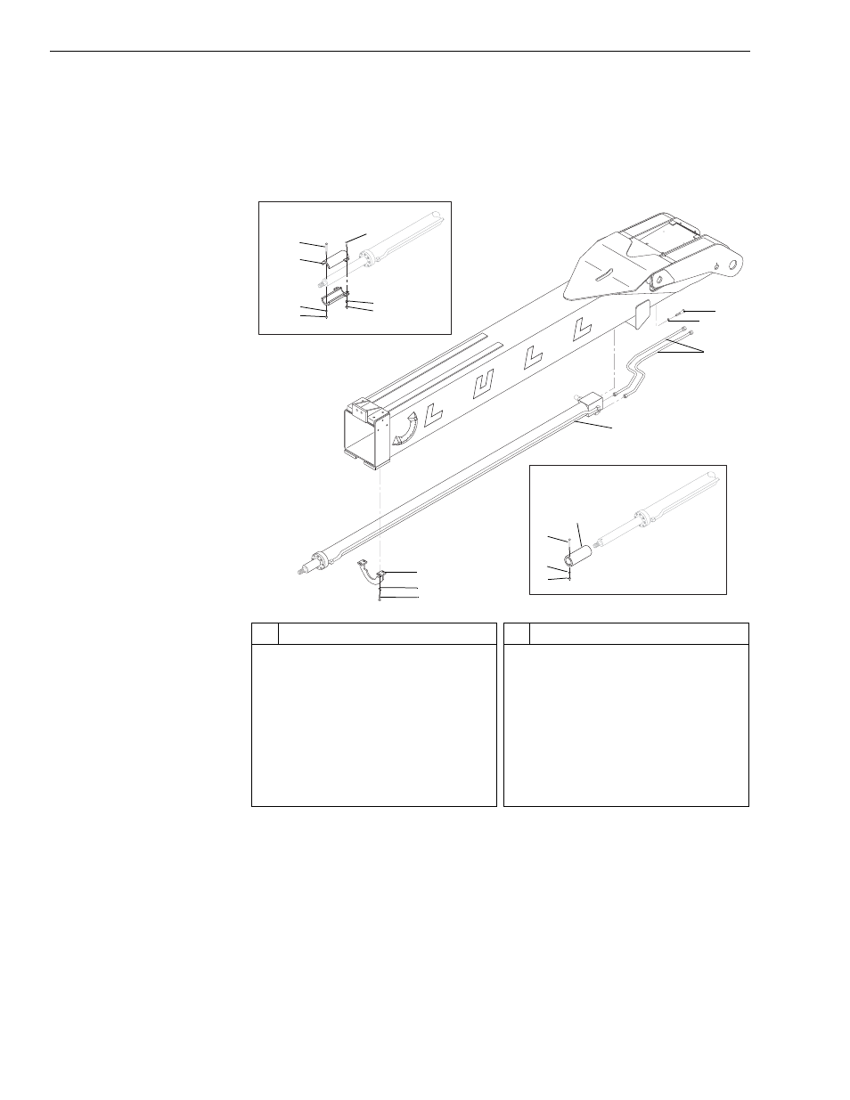
Fig. 6-134: Boom Extension Cylinder Removal – 3-Section Boom
21. (Ref. Fig. 6-117) Install the boom extension cylinder as follows:
a. If a new boom extension cylinder is being installed and the
machine being worked on has outriggers, install the cylinder stop
assembly as shown in View A or View B as follows:
For early production models (see View A),
1). Install cylinder stop halves (Item 2) on extension cylinder with
two (2) each capscrews (Item 5), lockwashers (Item 6), and
nuts (Item 7). Partially tighten the nuts.
0
80
6 0
4 0
2 0
- 2 0
J
1290
1
11
8
#
Description
1
Capscrew
2
Cylinder Stop
3
Lockwasher
4
Nut
5
Capscrew
6
Lockwasher
7
Nut
8
Cylinder Support Bracket
9
Lockwasher
#
Description
10 Capscrew
11 Cylinder Stop
12 Capscrew
13 Lockwasher
14 Nut
15 Capscrew
16 Lockwasher
17 Hydraulic Tube
18 Boom Extension Cylinder
View A – Models with Outriggers
(Early Production Models)
View B – Models with Outriggers
2
3
5
5
6
7
9
10
12
13
14
18
17
16
15