Lull 6K Service Manual User Manual
Page 473
Boom and Transfer
Service Manual — Models 644B, 6K, 844C, 8K, 1044C, 10K
6-223
e. Slowly lift the boom and transfer carriage assembly up and away
from the machine. Place the assembly on support blocks on a firm
level surface.
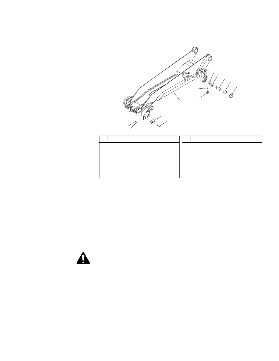
Fig. 6-238: Transfer Carriage Installation
13. The following steps are required if the boom is being removed
separately from the transfer carriage.
a. Remove the boom hoist cylinder (See page 6-12).
b. Remove the rear carriage tilt cylinder (See page 6-24).
c. Remove the boom (see this section).
d. Use sling(s), crane, or other suitable means to support the transfer
carriage assembly.
WARNING: To avoid personal and/or equipment damage, support the
transfer carriage assembly before removing any additional
mounting hardware. Use suitable blocking and lifting devices
when removing heavy machine components.
e. (Ref. Fig. 6-238) Remove the four (4) each nuts (Item 1) and
lockwashers (Item 2) securing the two (2) front slide blocks (Item 4)
to the transfer carriage (Item 5). Remove the four (4) capscrews
(Item 3) and the slide blocks.
f.
(Ref. Fig. 6-238) Loosen the two (2) setscrews (Item 6) in each
spindle nut (Item 7).
J
1154
1
#
Description
1
Nut
2
Lockwasher
3
Capscrew
4
Front Slide Block
5
Transfer Carriage
6
Setscrew
#
Description
7
Spindle Nut
8
Spacer Washer
9
Thrust Washer
10 Spindle
11 Roller Bushing
12 Transfer Roller
2
4
3
7
6
8
9
10
11
12
5