Lull 6K Service Manual User Manual
Page 151
Supply, Pressure, and Return Hydraulics
Service Manual — Models 644B, 6K, 844C, 8K, 1044C, 10K
5-7
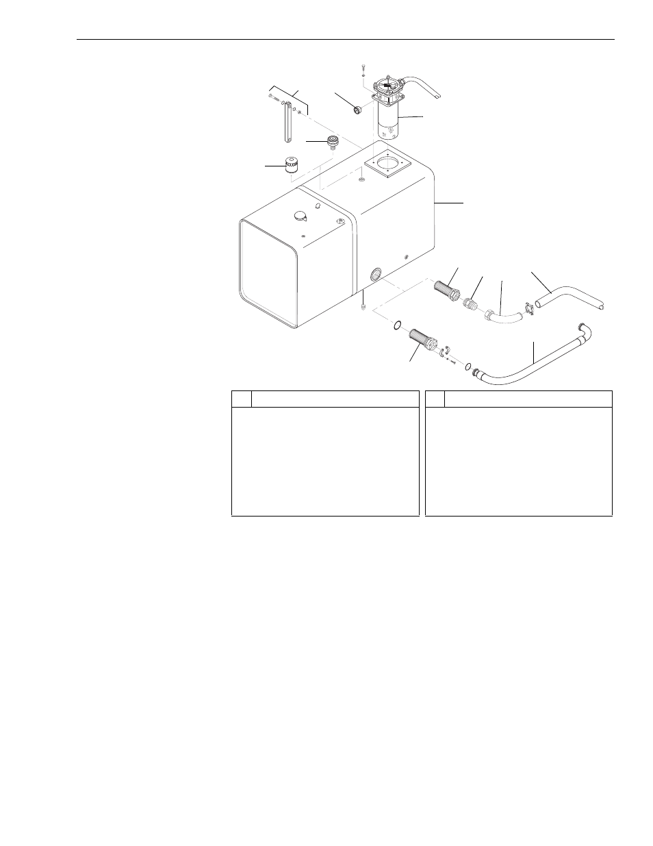
Fig. 5-5: Hydraulic Reservoir
(Ref. Fig. 5-5) The hydraulic system return filter assembly (Item 5), along
with the pressure gauge (Item 4), is located within the return filter housing,
located at the top of the reservoir (Item 6).
The strainer (Item 7 or Item 11) and suction line (Item 8, 9, and 10; or
Item 12) are located at the bottom of the back side of the reservoir.
A pressure differential gauge (Item 4) is fitted to the return filter housing to
monitor filter condition.
A breather filter assembly (Item 1 or Item 2) is threaded into the top of the
reservoir. It allows for expansion of fluid and prevents vacuum in the tank.
Check the hydraulic reservoir daily for the proper oil level. Maintain oil level
at the full mark on the sight gauge (Item 3) with all cylinders retracted.
Important: Do not operate the machine if the oil level falls below the low mark on
the sight gauge. Low oil level could damage the pump and other
components.
#
Description
1
Hydraulic Tank Breather (Models
with Mid-Inlet Hydraulics)
2
Hydraulic Tank Breather (Models
with Control Manifold Hydraulics)
3
Hydraulic Tank Sight Gauge
4
Pressure Gauge
5
Return Filter Assembly
6
Hydraulic Oil Tank
#
Description
7
Hydraulic Oil Strainer (Models with
Control Manifold Hydraulics)
8
Connector
9
Suction Tube
10 Suction Hose
11 Hydraulic Oil Strainer (Models with
Mid-Inlet Hydraulics)
12 Suction Line
2
3
4
5
6
7
9
K
1092
1
11
12
8
10