Selector valve (control manifold system) – Lull 6K Service Manual User Manual
Page 288
Boom and Transfer
6-38
Service Manual — Models 644B, 6K, 844C, 8K, 1044C, 10K
1. Install the four (4) elbows/tees (Items 5, 6, 8, and 9) on the ends of the
valves sections in the control valve assembly (Item 1), making sure
that they are positioned vertically so that the hydraulic hoses can be
easily reconnected through the holes in the valve plate. Torque to
25–29 ft-lbs.
2. Install the hydraulic return elbow (Item 4) and torque to109–121 ft-lbs.
3. Install the short connector (Item 2) and long connector (Item 3) into the
top of the control valves and torque the connectors to 105–115 ft-lbs.
4. Install the hydraulic tube connector (Item 7) into the side of the inlet
section housing of the control valve assembly (Item 1) and torque to
154-166 ft-lbs.
5. Perform a pressure test of the relief valve.
Selector Valve (Control Manifold System)
Description
644B-37 (S/N 101–590, 592–666)
644B-42 (S/N 101–207)
6K-37 (S/N 101–317)
6K-42 (S/N 101–119)
844C-42 (S/N 101–621)
8K-42 (S/N 101–220)
1044C-42 (S/N 101–116)
1044C-54 (S/N 101–154)
10K-42 (S/N 101–106)
10K-54 (S/N 101–103)
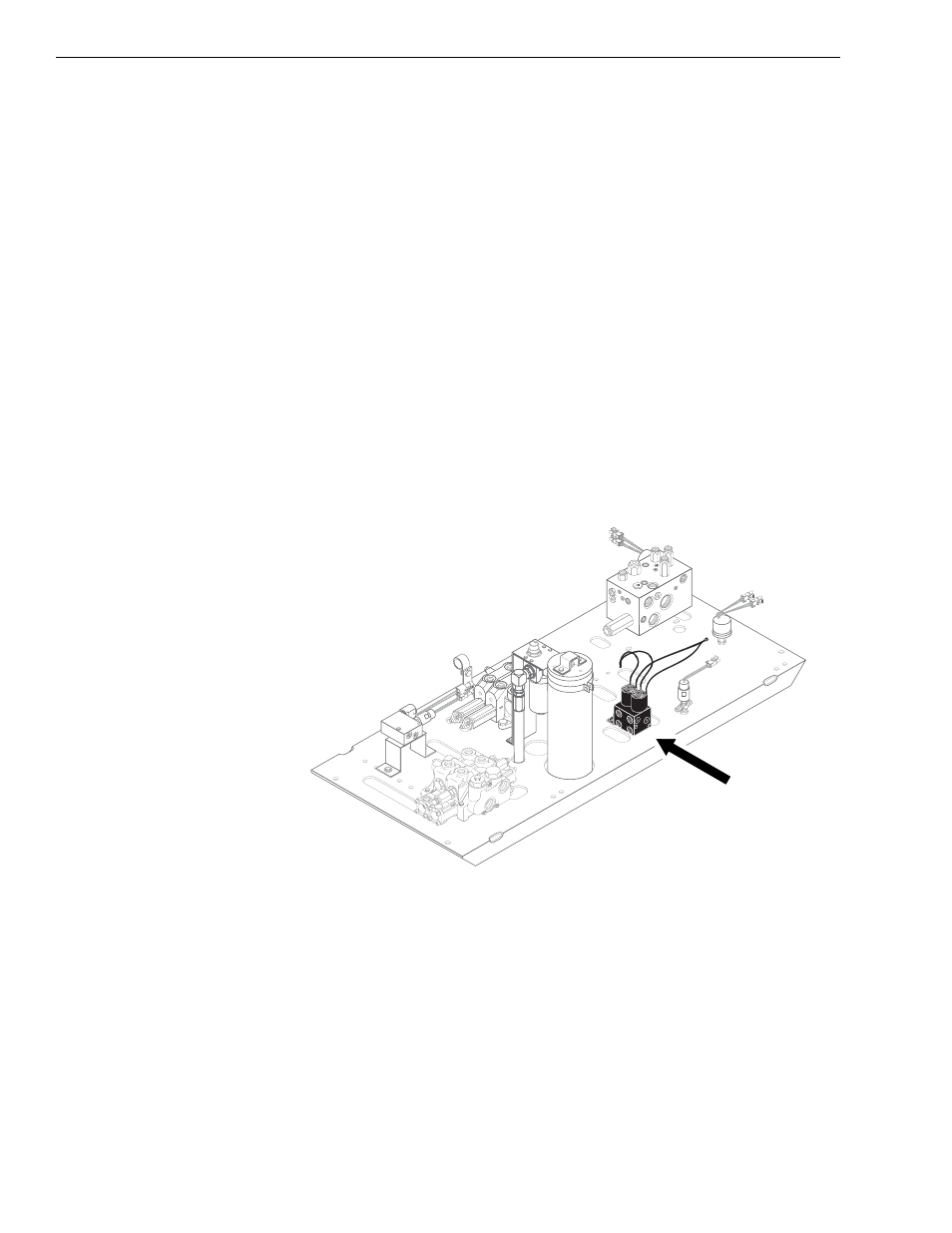
Fig. 6-23: Selector Valve – Models with Control Manifold Hydraulics
The 6-port circuit selector valve (directional control valve) is located on the
valve plate near the center of the machine. It directs fluid to the control
valve when the joystick is activated. The 6-port selector valve directs the
flow of hydraulic oil from the joystick controller to the appropriate control
valve section. The solenoids are used to change the flow of oil from one
control valve section to the other.
J
1
178