Hydraulic control manifold, Description – Lull 6K Service Manual User Manual
Page 208
Supply, Pressure, and Return Hydraulics
5-64
Service Manual — Models 644B, 6K, 844C, 8K, 1044C, 10K
Hydraulic Control Manifold
Description
6K-37 (S/N 101–317)
6K-42 (S/N 101–119)
8K-42 (S/N 101–220)
10K-42 (S/N 101–106)
10K-54 (S/N 101–103)
644B-37 (S/N 101–590, 592–666)
644B-42 (S/N 101–207)
844C-42 (S/N 101–621)
1044C-42 (S/N 101–116)
1044C-54 (S/N 101–154)
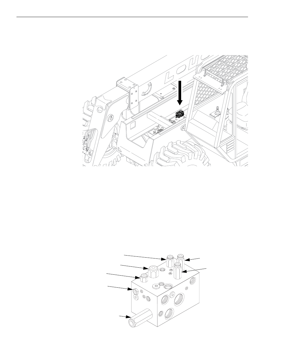
Fig. 5-40: Hydraulic Control Manifold Location
(Ref. Fig. 5-40) The hydraulic control manifold is located on the valve plate,
near the middle of the machine. This manifold controls hydraulic functions
using the following valves (see Fig. 5-41):
• Compensator Valve
• Check Valve
• Logic Valve
• Pilot Directional Valve
• Pilot Unloading Valve
• Pressure Reducing Valve
• Priority Flow Control
Fig. 5-41: Hydraulic Control Manifold Valves
0
80
60
40
20
-20
K
1064
K
115
0
Check Valve
Pilot Directional Valve
Pilot Unloading Valve
Pressure Reducing Valve
Priority Flow Control
Compensator Valve
Logic Valve