Lull 6K Service Manual User Manual
Page 472
Boom and Transfer
6-222
Service Manual — Models 644B, 6K, 844C, 8K, 1044C, 10K
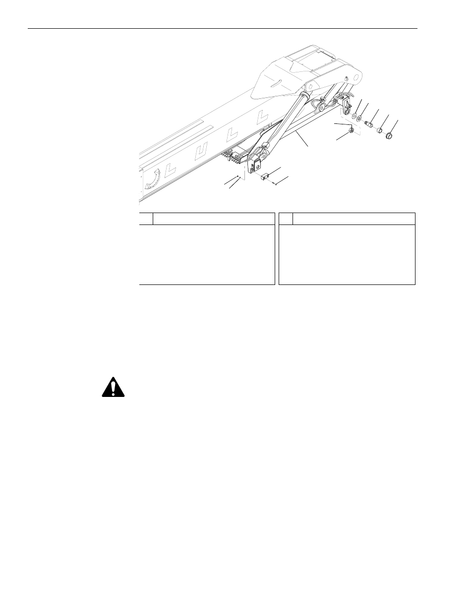
Fig. 6-237: Transfer Carriage with Boom Installation
12. (Ref. Fig. 6-237) The following steps are necessary if the boom and
transfer carriage are to be removed as an assembly.
a. Use sling(s), crane, or other suitable means to support the boom
and transfer carriage assembly. It will be necessary to fully secure
the transfer carriage securely to the boom before removal.
WARNING: To avoid personal and/or equipment damage, supporting the
boom and transfer carriage is essential before removing any
additional mounting hardware. Use suitable blocking and
lifting devices when removing heavy machine components.
b. Remove the four (4) each nuts (Item 1) and lockwashers (Item 2)
securing the front slide blocks (Item 4) to the transfer carriage
(Item 5). Remove the four (4) capscrews (Item 3) and the two (2)
slide blocks.
c. Loosen the two (2) setscrews (Item 6) in each spindle nut (Item 7).
d. Remove the two (2) each spindle nuts, spacer washers (Item 8),
thrust washers (Item 9), spindles (Item 10), roller bushings
(Item 11), and transfer rollers (Item 12) from the rear transfer
carriage mount.
Note: The quantity of spacer washers used with each machine may vary.
0
80
60
40
20
-20
J
1153
1
#
Description
1
Nut
2
Lockwasher
3
Capscrew
4
Front Slide Block
5
Transfer Carriage
6
Setscrew
#
Description
7
Spindle Nut
8
Spacer Washer
9
Thrust Washer
10 Spindle
11 Roller Bushing
12 Transfer Roller
2
4
3
7
6
8
9
10
11
12
5