Lull 6K Service Manual User Manual
Page 449
Boom and Transfer
Service Manual — Models 644B, 6K, 844C, 8K, 1044C, 10K
6-199
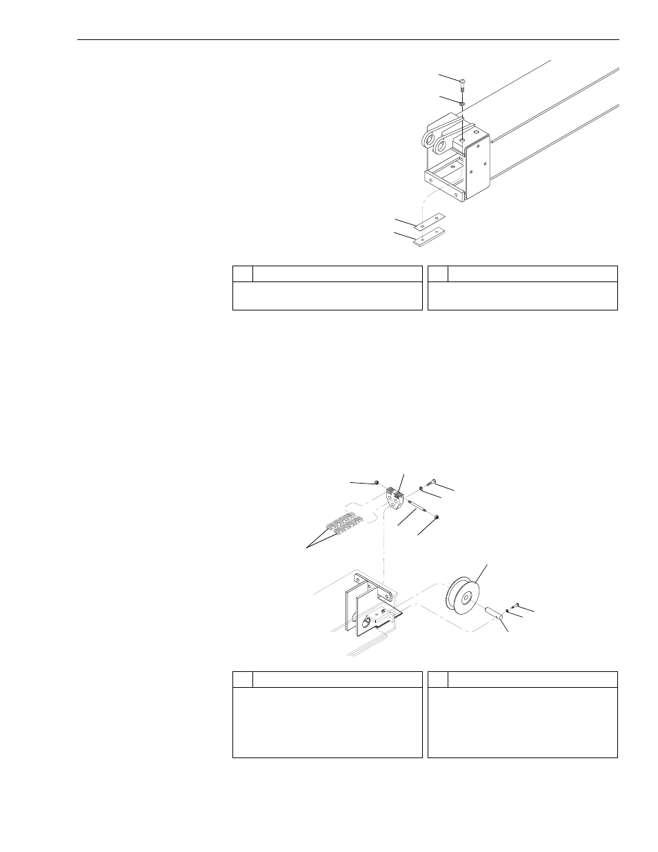
Fig. 6-213: Upper Slide Pad Installation – Front of Middle (Forward) Boom
Section
31. (Ref. Fig. 6-213) After applying thread locking compound to the
capscrews, install two (2) upper slide pads (Item 4) and shims (Item 3)
on front of middle (forward) boom section with lockwashers (Item 2)
and capscrews (Item 1) according to drawing specifications. Torque
capscrews to 180 in-lbs.
32. Lift middle (forward) and inner boom sections and slide them into
middle (rear) boom section.
Fig. 6-214: Upper Chain and Hose Reel Assembly – Middle (Forward) Boom
J
1245
1
2
3
4
#
Description
1
Button-Head Socket Capscrew
2
Lockwasher
#
Description
3
Shim
4
Front Upper Slide Pad
J
1244
7
8
9
10
1
2
2
3
6
5
4
#
Description
1
Upper Chains
2
Lock Nut
3
Upper Chain Anchor
4
Capscrew
5
Lockwasher
#
Description
6
Chain Anchor Rod
7
Hose Reel
8
Capscrew
9
Lockwasher
10 Hose Reel Pin