Lull 6K Service Manual User Manual
Page 441
Boom and Transfer
Service Manual — Models 644B, 6K, 844C, 8K, 1044C, 10K
6-191
10. (Ref. Fig. 6-204) Install chain and hose guide assembly on rear of
middle (rear) boom section as follows:
a. Install two (2) roller bushings (Item 1) inside chain and hose roller
(Item 12) — one in each end.
b. Install hardened bushing (Item 11) and two (2) chain roller washers
(Item 10) on the chain and hose roller.
c. Install two (2) each left hand hose guides (Item 8), plastic bushings
(Item 7), hose spacers (Item 6), washers (Item 2), and right hand
hose guides (Item 4) on chain and hose roller.
d. Install two hose guide spacers (Item 5) between left and right hand
hose guides with two (2) lock nuts (Item 9) and capscrews (Item 3).
Torque the lock nuts to 180 in-lbs.
e. Install chain and hose roller assembly on rear of boom section with
chain and hose roller shaft (Item 13).
f.
Install two (2) grease fittings (Item 14) and grease fittings covers
(Item 15) on chain and hose roller shaft.
11. Turn middle (rear) boom section over to upright position on work
stands.
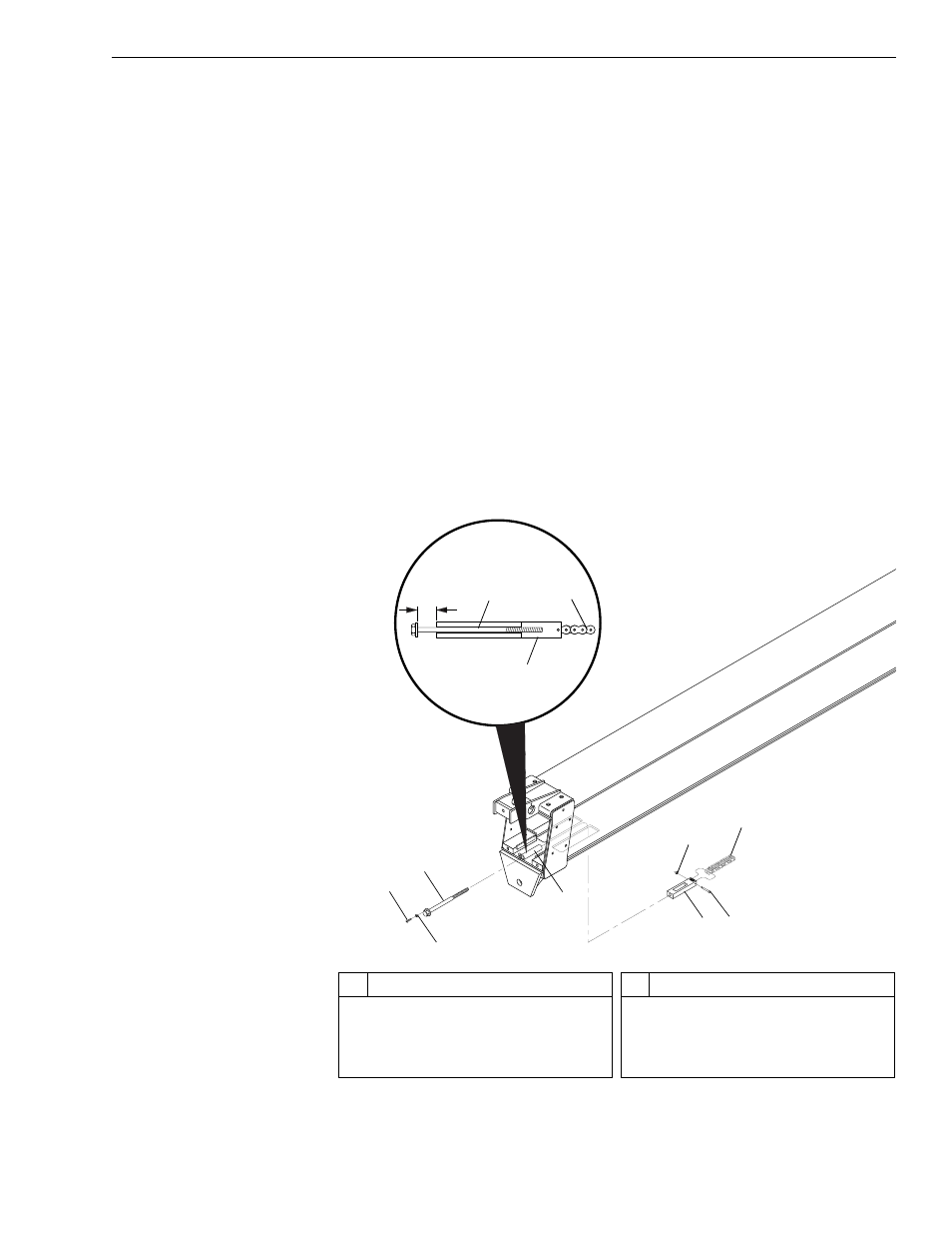
Fig. 6-205: Installation of Lower Chain – Middle (Rear) Boom Section
12. Install lower chain on bottom of middle (rear) boom section as follows:
J
1250
2
3
5
6
1
7
8
7
3
4
View A
3.13"
(3-1/8")
4
#
Description
1
Button-Head Socket Capscrew
2
Lockwasher
3
Chain Adjustment Rod
4
Anchor Base
#
Description
5
Chain Adjustment Block
6
Shoulder Bolt
7
Lock Nut
8
Chain