Lull 6K Service Manual User Manual
Page 286
Boom and Transfer
6-36
Service Manual — Models 644B, 6K, 844C, 8K, 1044C, 10K
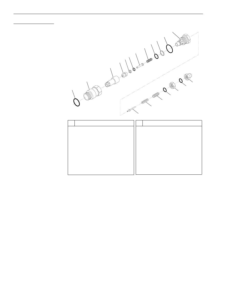
Relief Valve Assembly
Fig. 6-22: Relief Valve Assembly
(Ref. Fig. 6-22) The following steps are required to overhaul the relief valve
assembly.
1. Loosen and remove the rounded end nut (Item 19) with O-ring
(Item 18) from the adjusting screw (Item 15).
2. Loosen and remove the hex nut (Item 17) with O-ring (Item 16) from
the adjusting screw (Item 15).
3. Loosen and remove the plug assembly (Items 8 thru 12) from the valve
body assembly (Items 1 thru 7).
4. Remove spring (Item 8) from plug (Item 12).
5. Remove the adjusting screw (Item 15), spring (Item 14), and poppet
(Item 13) from plug.
Note: Record the number of turns that the adjusting screw was turned out.
6. Remove the poppet assembly (Items 3 thru 7) from the valve body
(Item 2).
#
Description
1
O-ring
2
Valve Body
3
Poppet
4
Poppet
5
Backup Ring
6
O-ring
7
Piston
8
Spring
9
O-ring
10 Backup Ring
#
Description
11 O-ring
12 Plug
13 Poppet
14 Spring
15 Adjusting Screw
16 O-ring
17 Hex Nut
18 O-ring
19 Rounded End Nut
1
2
4
3
5
6
7
8
9
10
11
12
19
18
17
16
15
14
13
06-9006