Multi-spool control valve, Description – Lull 6K Service Manual User Manual
Page 189
Supply, Pressure, and Return Hydraulics
Service Manual — Models 644B, 6K, 844C, 8K, 1044C, 10K
5-45
Multi-Spool Control Valve
Description
6K-37 (S/N 101–317)
6K-42 (S/N 101–119)
8K-42 (S/N 101–220)
10K-42 (S/N 101–106)
10K-54 (S/N 101–103)
644B-37 (S/N 101–590, 592–666)
644B-42 (S/N 101–207)
844C-42 (S/N 101–621)
1044C-42 (S/N 101–116)
1044C-54 (S/N 101–154)
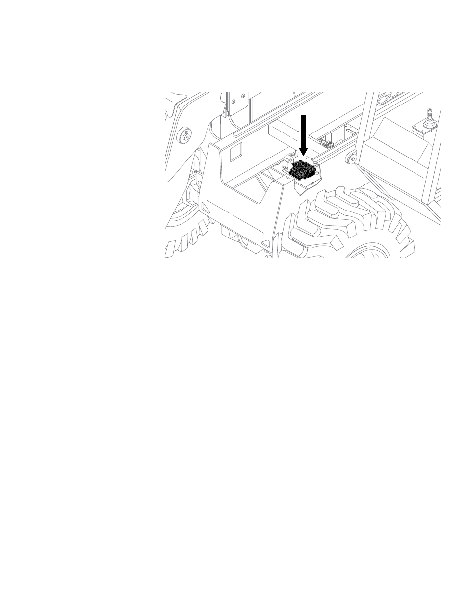
Fig. 5-28: Multi-Spool Control Valve Location
(Ref. Fig. 5-28) The multi-spool control valve is used on models with
control manifold hydraulics. It is located on the valve plate, near the middle
of the machine. This valve controls hydraulic functions for the following
circuits:
• Carriage (Attachment) Tilt
• 1st Auxiliary Hydraulics
• 2nd Auxiliary Hydraulics
• Frame Tilt
• Transfer Carriage
• L.H. Outrigger
• R.H. Outrigger
The presence of these circuits, and the controlling valve sections, depends
upon the machine model and installed options (See Figs. 5-29 and 5-30).
0
80
60
40
20
-20
K
104
6