Lull 6K Service Manual User Manual
Page 218
Supply, Pressure, and Return Hydraulics
5-74
Service Manual — Models 644B, 6K, 844C, 8K, 1044C, 10K
6. Clean valve cartridges using an solvent. Dry with compressed air.
7. Make sure that you have the correct O-ring kit for each cartridge valve
ensuring they are not damaged. Lubricate each O-ring with hydraulic
oil before installing it on cartridge valve. Install the largest (black)
O-ring first. Install remaining O-rings in descending order, making sure
largest is installed first and smallest last.
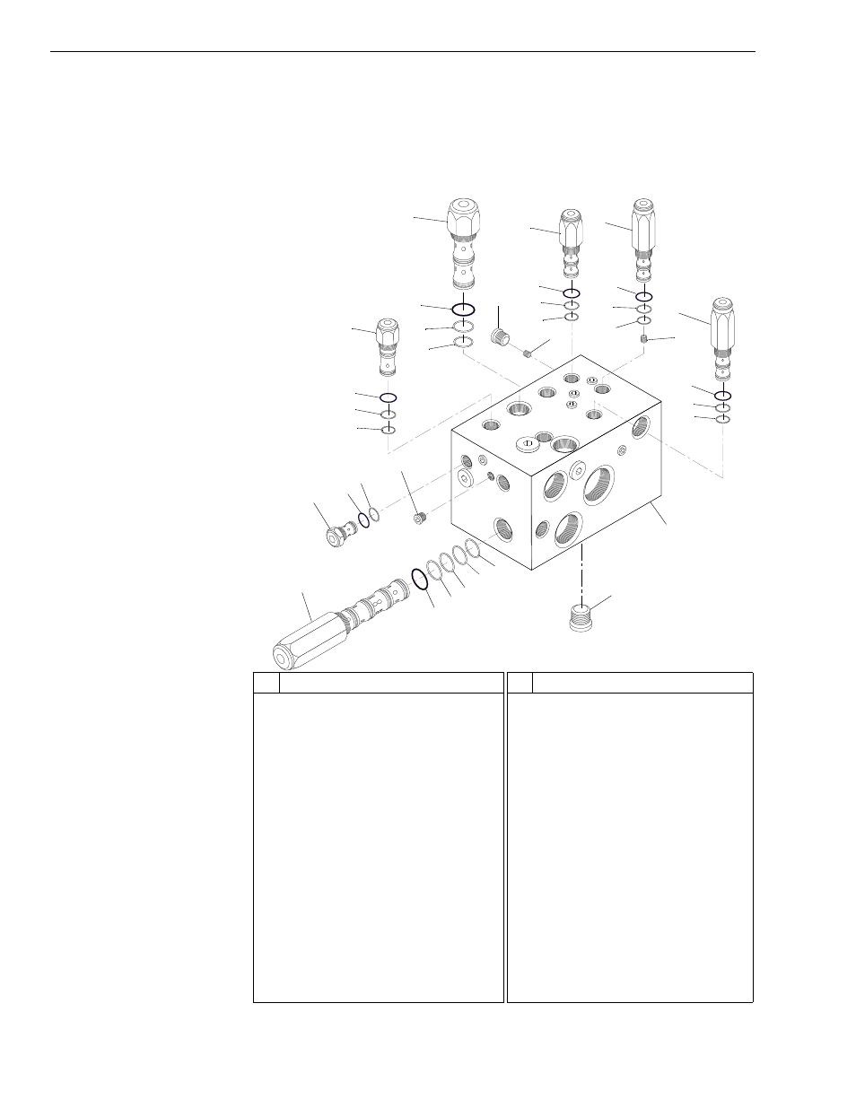
Fig. 5-45: Hydraulic Control Manifold Assembly
K
1063
11
12
13
14
9
8
7
10
19
15
20
24
23
22
21
25
26
27
28
20
29
30
31
32
33
34
6
5
4
3
2
1
16
17
18
#
Description
1
Compensator Valve Cartridge
2
O-Ring
3
O-Ring
4
O-Ring
5
O-Ring
6
O-Ring
7
Check Valve Cartridge
8
O-Ring
9
O-Ring
10 Hollow Hex O-Ring Plug
11 Poppet Type Logic Valve Cartridge
12 O-Ring
13 O-Ring
14 O-Ring
15 Priority Flow Control Cartridge
16 O-Ring
17 O-Ring
#
Description
18 O-Ring
19 Hollow Hex O-Ring Plug
20 Orifice Plug
21 Pilot Directional Valve Cartridge
22 O-Ring
23 O-Ring
24 O-Ring
25 Press. Reducing Valve Cartridge
26 O-Ring
27 O-Ring
28 O-Ring
29 Pilot Unloading Valve Cartridge
30 O-Ring
31 O-Ring
32 O-Ring
33 Hydraulic Control Manifold Block
34 Hollow Hex O-Ring Plug