Lull 6K Service Manual User Manual
Page 442
Boom and Transfer
6-192
Service Manual — Models 644B, 6K, 844C, 8K, 1044C, 10K
a. Install chain adjustment block (Item 5) on lower chain with shoulder
bolt (Item 6) and lock nut (Item 7). Torque lock nut to 108 in-lbs.
b. Position chain adjustment block tight against back of anchor base
(Item 4) at bottom of middle (rear) boom section as shown in View
A.
c. Thread chain adjustment rod (Item 3) into block until specified
measurement is obtained.
d. Push adjustment rod fully into anchor base.
e. Lay chain flat inside of middle (rear) section. Attach a cord or wire
to end of chain for ease in handling after all four sections are
assembled.
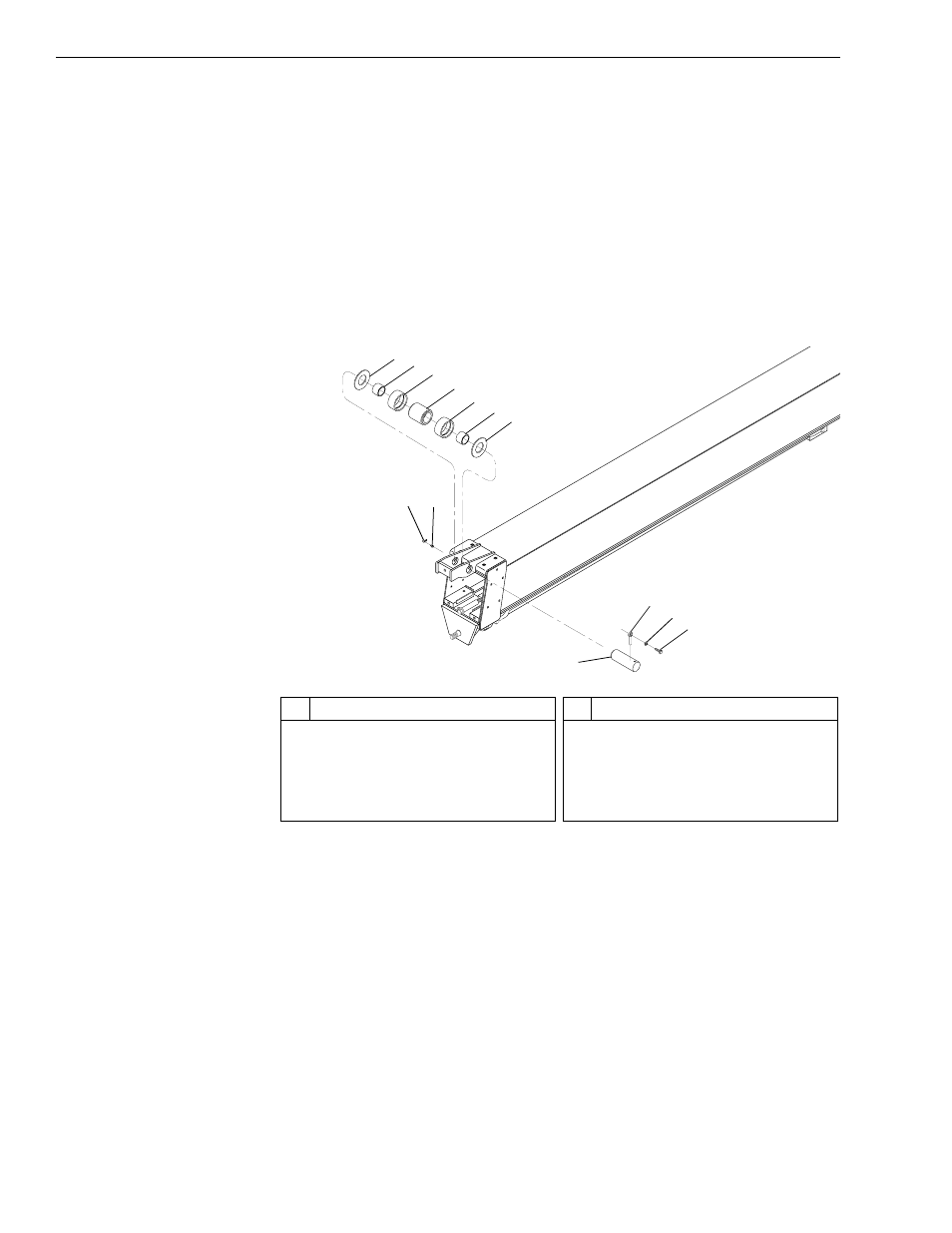
Fig. 6-206: Upper Chain Roller Assembly – Middle (Rear) Boom Section
13. (Ref. Fig. 6-206) Install upper chain roller assembly on middle (rear)
boom section as follows:
a. Install two (2) chain roller bushings (Item 2) into chain roller
(Item 4).
b. Install two (2) hardened bushings (Item 3) on chain roller.
c. Install bushings and chain roller and two (2) chain guide washers
(Item 1) on front of middle (forward) boom section with chain roller
pin (Item 10).
d. Secure chain roller pin with lock pin (Item 7), lockwasher (Item 8),
and capscrew (Item 9). Torque capscrew to 110 ft-lbs.
J
1254
5
1 2
7
8
9
10
3
4
3
2
1
6
#
Description
1
Chain Guide Washer
2
Chain Roller Bushing
3
Hardened Bushing
4
Chain Roller
5
Grease Fitting Cover
#
Description
6
Grease Fitting
7
Lock Pin
8
Lockwasher
9
Capscrew
10 Chain Roller Pin