Lull 6K Service Manual User Manual
Page 542
Frame Tilt and Oscillation
7-40
Service Manual — Models 644B, 6K, 844C, 8K, 1044C, 10K
Removal
Frame Tilt Lockout Valve
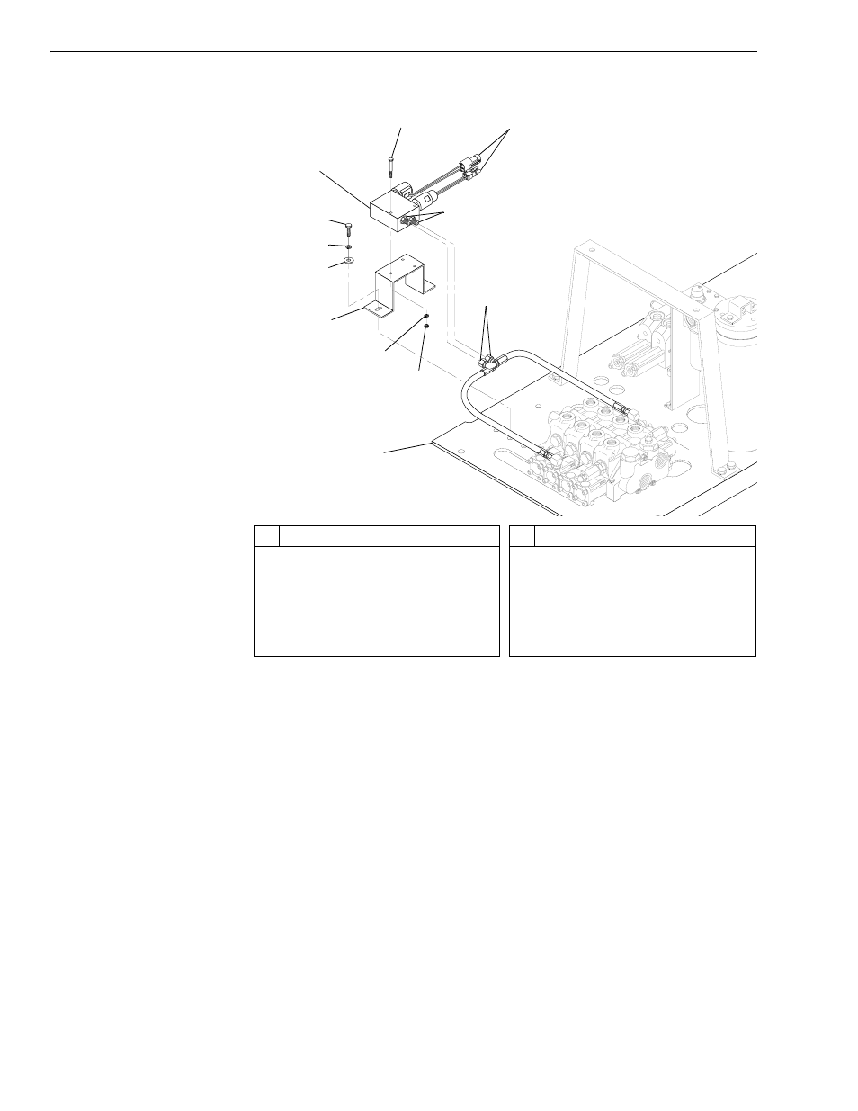
Fig. 7-24: Frame Tilt Lockout Valve Installation
(Ref. Fig. 7-24) The following procedure describes removal of the frame tilt
lockout valve.
1. Follow preparation procedures as outlined in Section 3.
2. Tag and disconnect two (2) hydraulic hoses (Item 11) from connectors
(Item 12) at frame tilt lockout valve (Item 3). Cap fittings and hoses.
3. Disconnect electrical leads (Item 1).
4. Remove two (2) capscrews (Item 4), lockwashers (Item 5), and
flatwashers (Item 6) securing mounting bracket (Item 7) to valve plate
(Item 10). Remove mounting bracket with lockout valve.
5. Remove two (2) capscrews (Item 2), lockwashers (Item 8), and nuts
(Item 9) securing lockout valve to mounting bracket. Separate valve
and bracket.
K
1032
3
1
2
4
5
6
8
9
10
7
#
Description
1
Electrical Leads
2
Capscrew
3
Frame Tilt Lockout Valve
4
Capscrew
5
Lockwasher
6
Flatwasher
#
Description
7
Mounting Bracket
8
Lockwasher
9
Nut
10 Valve Plate
11 Hydraulic Hose
12 Connector
11
12