Lull 6K Service Manual User Manual
Page 406
Boom and Transfer
6-156
Service Manual — Models 644B, 6K, 844C, 8K, 1044C, 10K
8. (Ref. Fig. 6-169) Tag and disconnect two (2) hoses at boom extension
cylinder lines (Item 3). Cap lines and hoses.
Note: “K” Model machines are not equipped with auxiliary hydraulics. For these
models, disregard procedures that refer to auxiliary hydraulic components.
9. Tag and disconnect two (2) carriage tilt hoses (Item 2), and two (2)
auxiliary hydraulics hoses (Item 1) at the boom. Cap hoses and lines.
10. Place sling around inner boom section, at the front. Chains with hooks
may be attached to the rear of the outer boom section, near the pivot
pin bosses (Ref. Fig. 6-170). Attach sling and chains to crane hook
and lift crane to support weight of boom.
CAUTION: Make sure crane, slings, and chains have sufficient capacity to
support the weight of the boom. A 4-section boom assembly,
including boom extension cylinder, weighs approximately
6,650 pounds.
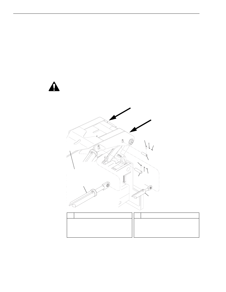
Fig. 6-170: Cylinder Pivot Pins
11. (Ref. Fig. 6-170) Remove four (4) capscrews (Item 3) and lockwashers
(Item 2) from lock pins (Item 1) securing rear carriage tilt cylinders
(Item 6) and boom hoist cylinders (Item 7) to the boom (Item 8).
Remove four (4) lock pins from pivot pins (Items 4 and 5).
J
1221
3
1
2
3
4
2
1
5
6
7
8
Hook chains at
these areas
#
Description
1
Lock Pin
2
Lockwasher
3
Bolt
4
Pivot Pin, Rear Carriage Tilt Cyl.
#
Description
5
Pivot Pin, Boom Hoist Cylinder
6
Rear Carriage Tilt Cylinder
7
Boom Hoist Cylinder
8
Boom