Lull 6K Service Manual User Manual
Page 334
Boom and Transfer
6-84
Service Manual — Models 644B, 6K, 844C, 8K, 1044C, 10K
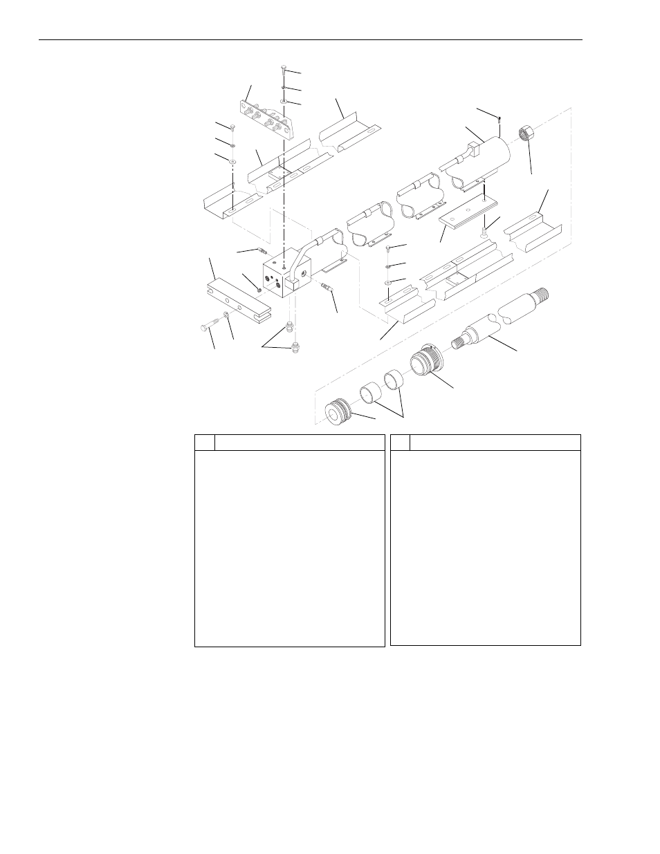
Fig. 6-86: 2-Section Boom Extension Cylinder Assembly
12. (Ref. Fig. 6-86) Remove the two capscrews (Item 6), lockwashers
(Item 7), and flatwashers (Item 8) securing the hose mounting bracket
(Item 5) to the cylinder manifold. Remove the hose mounting bracket.
13. (Ref. Fig. 6-86) Remove the two (2) capscrews (Item 10) and
lockwashers (Item 11) securing the rear mount support (Item 12) to the
cylinder manifold. Remove the rear mount support.
J
113
5
#
Description
1
Capscrew
2
Lockwasher
3
Flatwasher
4
Rear Hose Tray - R.H.
5
Hose Mounting Bracket
6
Capscrew
7
Lockwasher
8
Flatwasher
9
Front Hose Tray
10 Capscrew
11 Lockwasher
12 Rear Mount Support
13 Hollow Hex O-ring Plug
14 Counterbalance Valve Cartridge
#
Description
15 O-ring Connector
16 Counterbalance Valve Cartridge
17 Cylinder Barrel
18 Setscrew
19 Slide Plate
20 Flat Head Socket Screw
21 Rod Nut
22 Front Hose Tray
23 Rear Hose Tray - L.H.
24 Piston
25 Stroke Limiter
26 Rod Bearing Head
27 Cylinder Rod
13
1
15
14
19
20
24
25
21
26
27
16
2
3
1
2
3
4
22
9
23
5
8
7
6
18
17
12
10
11