Lull 6K Service Manual User Manual
Page 348
Boom and Transfer
6-98
Service Manual — Models 644B, 6K, 844C, 8K, 1044C, 10K
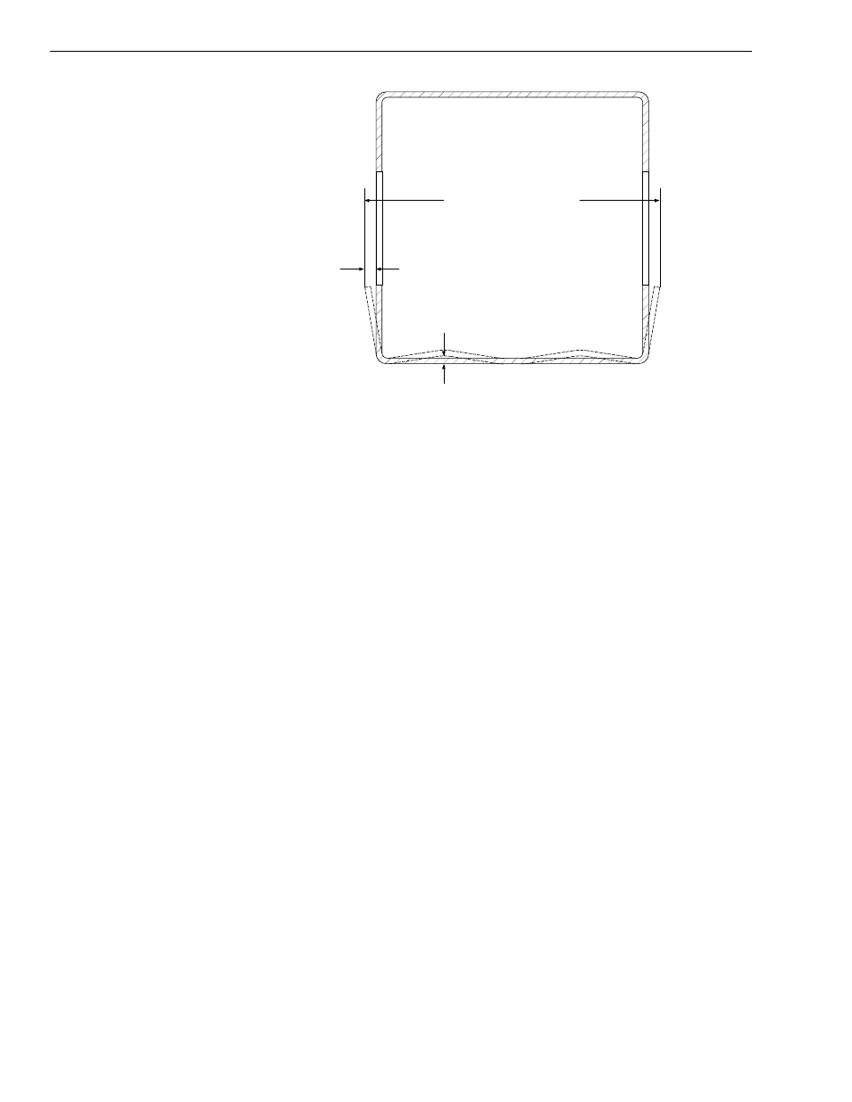
Fig. 6-101: Middle Boom Cross-Section at Window
4. (Ref. Fig. 6-101) Place a straight edge against the bottom surface of
the middle boom section. Measure the distance from the straight edge
to the bottom surface of the boom tube. This distance should not
exceed 1/4" (0.25"). The maximum deflection will be found just in front
of the outer boom section.
5. (Ref. Fig. 6-101) The side walls may also deflect outward at the
window areas. Take this measurement across the middle boom tube,
through the windows. Maximum allowable deflection is 3/16" (0.19")
per side. The maximum allowable middle boom tube width is 14-3/8"
(14.38"), measured through the windows.
Removal and Disassembly
3-Section Boom
1. Follow safety guidelines as outlined in Section 1 of this manual. Make
sure to park the machine on a level surface and use appropriate tools
when working with heavy equipment. Always make sure to follow
safety precautions when dealing with hydraulic fluid under pressure.
2. Remove attachment. See page 6-54.
3. Remove the Quick Attach. See page 6-58.
4. Retract the front carriage tilt cylinder all the way in.
5. Position the boom horizontally, pull the park brake, shut off the engine,
and remove the key.
6. Loosen and remove the chain anchor adjustor from the top front of the
outer boom. Machines were manufactured with three types of chain
anchors. These are shown below. Follow the steps for the machine
with the appropriate serial number.
1/4" (0.25") Max.
3/16" (0.19")
J1085
14 3/8" (14.38") Max.