Lull 6K Service Manual User Manual
Page 225
Supply, Pressure, and Return Hydraulics
Service Manual — Models 644B, 6K, 844C, 8K, 1044C, 10K
5-81
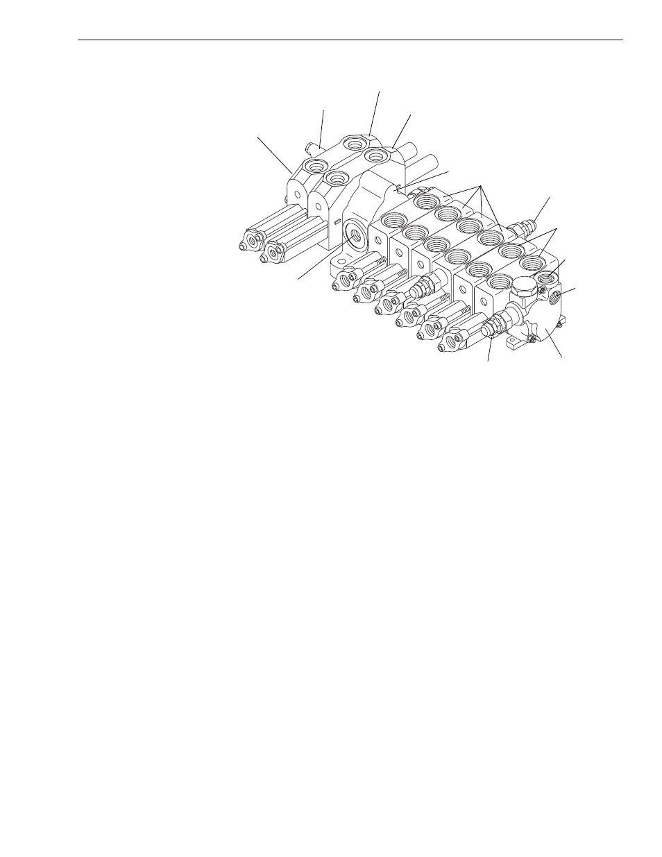
Fig. 5-50: Mid-Inlet Control Valve Components
(Ref. Fig. 5-49 and Fig. 5-50)The mid-inlet control valve is located on the
valve plate, near the middle of the machine. This valve controls hydraulic
functions for the following circuits:
• L.H. Outrigger
• R.H. Outrigger
• Carriage Fork Tilt
• Transfer Carriage
• 1st Auxiliary Hydraulics
• 2nd Auxiliary Hydraulics
• Frame Tilt
• Unloader (Used on 6K and 644B models with natural engines)
To the right of the mid-inlet section, there are two boom-controlling
sections for the following circuits:
• Boom Hoist
• Boom Extension (Telescope)
The presence of these circuits, and the controlling valve sections, depends
upon the machine model and installed options (see Fig. 5-51 and
Fig. 5-52).
K
114
1
Mid-Inlet
Outlet Section
Boom Extension
Boom Hoist
Relief Valve
“Pump 2”
Test Port
Relief Valve
Inlet (From Priority
Valve on Pump)
Outlet
(Return to Tank)
Work Ports
Inlet Section
Inlet From
Pump 2
Valve Sections