Lull 6K Service Manual User Manual
Page 434
Boom and Transfer
6-184
Service Manual — Models 644B, 6K, 844C, 8K, 1044C, 10K
Note: This procedure assumes that the boom has been completely
disassembled. In certain areas, references are made to other
locations in this manual where specific subjects are covered in
detail.
Note: “K” Model machines are not equipped with auxiliary hydraulics. For
these models, disregard procedures that refer to auxiliary hydraulic
components. Models that are equipped with an additional set of
auxiliary hydraulics will have two (2) more sets of hoses, tubes, and
mounting hardware than what is mentioned in the following
procedures.
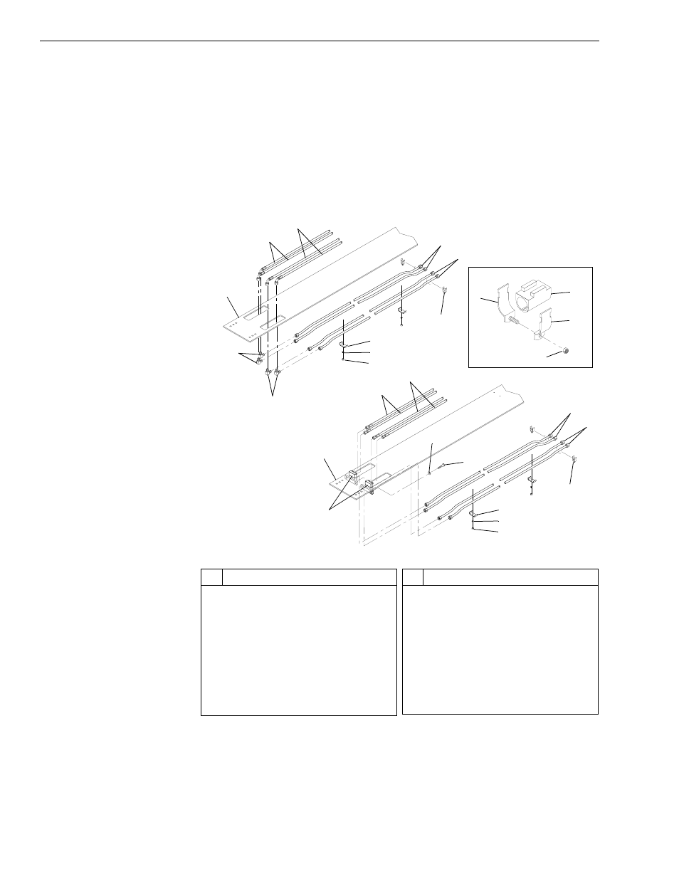
Fig. 6-199: Outer Boom Tube and Hose Assembly
2. (Ref. Fig. 6-199) Install auxiliary and front carriage tilt hydraulic tubes
and hoses on outer boom section as follows:
For Models 1044C-53 (S/N 101–144 and 148) and
10K-54 (S/N 101– 102):
J
124
0
#
Description
1
Outer Boom Section
2
Auxiliary Hydraulic Hose
3
Carriage Tilt Hydraulic Hose
4
Elbow
5
Nut
6
Lockwasher
7
Clamp
8
Cushion Clamp
9
Auxiliary Hydraulic Tube
#
Description
10 Carriage Tilt Hydraulic Tube
11 Hydraulic Manifold Block
12 Lockwasher
13 Capscrew
14 Left Clamp Half
15 Plastic Cushion
16 Right Clamp Half
17 Lock Nut
1
2
3
4
4
5
6
7
10
9
8
1
2
3
10
7
6
5
11
12
13
8
9
14
15
16
17
View A
J
1249
1044C-54 (S/N 101–144 and 148)
1044C-54 (S/N 145–147, and 149–)
10K-54 (S/N 101–102)
10K-54 (S/N 103–)