Overhaul – Lull 6K Service Manual User Manual
Page 508
Frame Tilt and Oscillation
7-6
Service Manual — Models 644B, 6K, 844C, 8K, 1044C, 10K
Overhaul
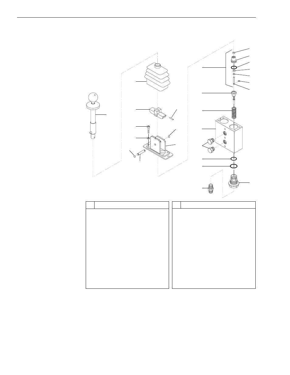
Frame Tilt Control Valve
Fig. 7-4: Frame Tilt Control Valve (Exploded View)
(Ref. Fig. 7-4) The following procedures are for the disassembly, cleaning,
and assembly of the frame tilt control valve. Follow the guidelines for
cleanliness as stated in Section 3 of this manual.
#
Description
1
Lever Assembly
2
Rubber Boot
3
Cam
4
Roll Pin
5
Capscrew (4)
6
Washer (4)
7
Circlip (2)
8
Pivot Pin
9
Flange
10 Guide Assembly (2) (Incl. 11–17)
11 Wiper
12 Guide
13 O-Ring
#
Description
14 Seal
15 Spreader
16 Circlip
17 Plunger
18 Spool Assembly (2)
19 Spring (2)
20 Valve Body
21 Plug, O-Ring
22 O-Ring (2)
23 O-Ring (2)
24 Ported Guide (2)
25 Fitting, O-Ring
K
1022
1
2
3
4
5
6
7
7
8
9
10
11
12
13
14
15
16
17
18
19
20
21
22
24
23
25