Lull 6K Service Manual User Manual
Page 423
Boom and Transfer
Service Manual — Models 644B, 6K, 844C, 8K, 1044C, 10K
6-173
c. (Ref. Fig. 6-187) Remove lower slide pads from front of middle
(forward) boom section as follows:
For Models 1044C-54 (S/N 101–154) and 10K-54 (S/N 101–103):
1). Remove two (2) each capscrews (Item 19) and lockwashers
(Item 20) along with the pad retainer (Item 18) (see View A).
2). Remove two (2) socket capscrews (Item 9) and lockwashers
(Item 10) securing lower slide pads (Item 1) to front of boom
section.
3). Remove slide pads and shims (Item 2).
For Models 1044C-54 (S/N 155–) and 10K-54 (S/N 104–):
1). Remove two (2) socket capscrews (Item 9) and lockwashers
(Item 10) securing lower slide pads (Item 1) to front of boom
section.
2). Remove slide pads and shims (Item 2).
21. (Ref. Fig. 6-187) Remove two (2) capscrews (Item 14) and
lockwashers (Item 15) securing bottom slide pad (Item 17) to rear of
middle (forward) boom section. Remove slide pad and shim(s)
(Item 16).
22. Slide inner boom section out of middle (forward) boom section. Place
inner boom on work stands in upright position.
23. Remove auxiliary hydraulic quick disconnects from inner boom.
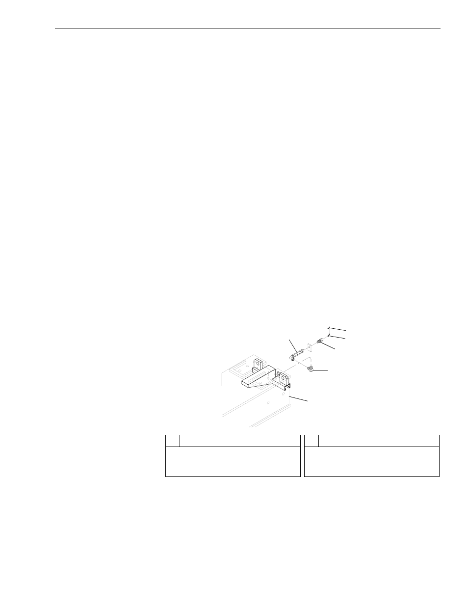
Fig. 6-188: Grease Hose Assembly
24. (Ref. Fig. 6-188) Remove bulkhead adapter (Item 4) from rear of inner
boom section (Item 2).
25. (Ref. Fig. 6-188) Loosen and remove grease hose (Item 1) and elbow
(Item 3) from inside of inner boom section.
26. Flip middle (forward) boom section to upright position.
J
1235
3
5
1
4
6
2
#
Description
1
Grease Hose
2
Inner Boom Section
3
Elbow
#
Description
4
Bulkhead Adapter
5
Grease Fitting
6
Grease Fitting Cover