Lull 6K Service Manual User Manual
Page 587
Brakes
Service Manual — Models 644B, 6K, 844C, 8K, 1044C, 10K
9-13
Service Brake Adjustment Procedures
Models with Control Manifold Hydraulics
6K-42 (S/N 101–119)
8K-42 (S/N 101–220)
10K-42 (S/N 101–106)
10K-54 (S/N 101–103)
644B-37 (S/N 101–590, 592–666)
644B-42 (S/N 101–207)
844C-42 (S/N 101–521)
1044C-42 (S/N 101–116)
1044C-54 (S/N 101–154)
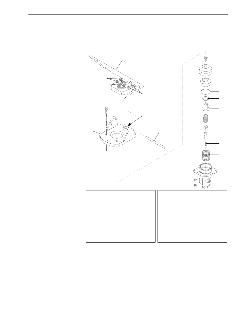
Fig. 9-8: Service Brake Adjustment – Models with Control Manifold
Hydraulics
The following brake adjustment procedure refers to Fig. 9-8.
1. With the engine off, connect a 0–600 psi gauge to the test port marked
“Brakes” located behind the cab step.
2. Pump the brakes until the gauge reads 0 psi; remove the gauge.
#
Description
1
Brake Pedal
2
Hex Nut
3
Deadband Setscrew
4
U-Clamp
5
Actuator Base
6
Pedal Mounting Pin
7
Flange Head Capscrew
8
Rubber Boot
9
Piston Guide
#
Description
10 O-Ring
11 Seal
12 Piston
13 Regulator Spring
14 Spring Seat
15 Spool
16 Spool Return Spring
17 Piston Return Spring
18 Body
V
1103
1
2
2
3
6
5
8
7
10
9
11
12
13
14
15
16
17
18
4
Place a .010”
Shim Here
(See Step 21)