Lull 6K Service Manual User Manual
Page 608
Brakes
9-34
Service Manual — Models 644B, 6K, 844C, 8K, 1044C, 10K
6. Tag and slowly loosen hydraulic hoses (Items 6, 11 and 14) from elbow
(Item 5), check valve (Item 12), and connector (Item 13). Bleed any
remaining oil into appropriate container. Disconnect hoses. Cap hoses
and fittings.
7. Loosen and remove the two (2) each capscrews (Item 1) and
lockwashers (Item 2) that secure the park brake valve (Item 4) to the
instrument panel (Item 3).
8. Remove the park brake valve and take it to a clean area appropriate for
further cleaning and disassembly.
9. Remove elbow (Item 5), check valve (Item 12), and connector
(Item 13) from park brake valve (Item 4). Clean with appropriate
solvent and dry with compressed air. Replace any damaged parts.
10. Disassemble, inspect, and repair park brake valve as described below
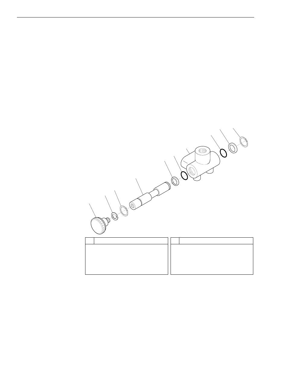
and shown in Fig. 9-20.
Fig. 9-20: Park Brake Valve Assembly
a. Remove snap ring (Item 10) from valve spool (Item 4).
b. Remove valve spool assembly (Items 1–4) from the valve housing
(Item 7).
c. Remove snap ring (Item 3) from valve spool.
d. Remove O-rings (Items 6 and 8) and backup rings (Items 5 and 9)
from valve housing.
e. Discard O-rings, backup rings, and snap rings.
#
Description
1
Control Knob
2
Lockwasher
3
Snap Ring
4
Valve Spool
5
Teflon Backup Ring
#
Description
6
O-Ring
7
Valve Housing
8
O-Ring
9
Teflon Backup Ring
10 Snap Ring
08-9003
1
2
3
4
5
6
7
8
9
10