Lull 6K Service Manual User Manual
Page 239
Supply, Pressure, and Return Hydraulics
Service Manual — Models 644B, 6K, 844C, 8K, 1044C, 10K
5-95
Models with a Mid-Inlet Hydraulic System
6K-37 (S/N 318–)
6K-42 (S/N 120–)
8K-42 (S/N 221–)
10K-42 (S/N 107–)
10K-54 (S/N 104–)
644B-37 (S/N 591, 667–)
644B-42 (S/N 208–)
844C-42 (S/N 622–)
1044C-42 (S/N 117–)
1044C-54 (S/N 155–)
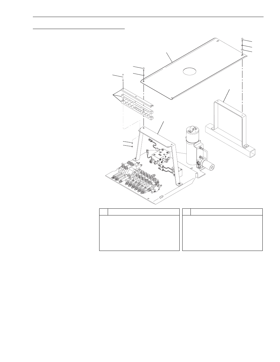
Fig. 5-62: Roll-Back Tray Installation - Mid-Inlet Hydraulics
(Ref. Fig. 5-62) The following procedure describes removal of the roll-back
hose tray used in models with a mid-inlet hydraulic system.
1. Remove the two (2) each button head socket capscrews (Item 6) and
lockwashers (Item 7) securing the roll-back hose tray (Item 8) to the
front hose tray support bracket (Item 3).
2. Remove the two (2) each button head socket capscrews (Item 9),
lockwashers (Item 10), and flatwashers (Item 11) securing the roll-
back hose tray to the rear hose tray support bracket (Item 12).
3. Remove the roll-back hose tray from the machine.
#
Description
1
Nut
2
Lockwasher
3
Front Hose Tray Support Bracket
4
Hose Mount
5
Button Head Socket Capscrew
6
Button Head Socket Capscrew
#
Description
7
Lockwasher
8
Roll-Back Hose Tray
9
Button Head Socket Capscrew
10 Lockwasher
11 Flatwasher
12 Rear Hose Tray Support Bracket
5
K
1152
4
2
1
7
6
8
3
12
11
10
9