Lull 6K Service Manual User Manual
Page 484
Boom and Transfer
6-234
Service Manual — Models 644B, 6K, 844C, 8K, 1044C, 10K
b. Remove six (6) each nuts (Item 3), lockwashers (Item 1), and
flatwashers (Item 2) securing boom cover (Item 4) to boom.
Remove boom cover.
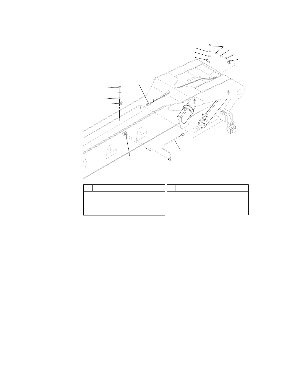
Fig. 6-248: Boom Extension Proximity Switch Wiring
5. (Ref. Fig. 6-248) For models with a 4-section boom, remove the boom
extension proximity switch as follows:
a. Remove the six (6) each (five on top of the boom and one inside of
the back left side of the boom) nuts (Item 4), lockwashers, (Item 3)
flatwashers (Item 2), and J-clamps (Item 1) that secure the boom
extension proximity switch wiring to the boom.
b. Disconnect the proximity switch connection wire (Item 6) from the
proximity switch (Item 7) and the wiring harness (Item 5).
c. Remove all wire ties that secure the wiring harness to hydraulic
tubes and hoses so that it is completely separated from the transfer
carriage.
0
80
60
40
20
#
Description
1
J-Clamp
2
Flatwasher
3
Lockwasher
4
Nut
#
Description
5
Proximity Switch Wiring Harness
6
Proximity Switch Connection Wire
7
Boom Extension Proximity Switch
J1
1
4
7
4
3
1
5
3
2
1
6
7
2
4
3
2
1