Lull 6K Service Manual User Manual
Page 569
Transmission
Service Manual — Models 644B, 6K, 844C, 8K, 1044C, 10K
8-21
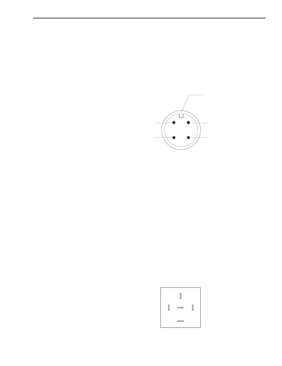
Rear Oscillation Lock Proximity Switch Integrity Test
1. Disconnect the plug connecting the wire harness at the proximity
switch.
2. Remove the proximity switch from the transfer carriage by loosening
and removing the jam nut on the inside of the transfer carriage.
3. Reference the wire harness end of the proximity switch to note the
connection guide and the position of the four pins as shown in
Fig. 8-10.
Fig. 8-10: Connection Guide and Pin Positions
4. Connect a 12 volt power lead to the (A) pin.
5. Connect a wire lead to (C) pin and ground this lead. With the proximity
switch not sensing metal, there should not be a 12 volt signal at pin (B).
If a 12 volt signal is detected at pin (B), remove and replace the
proximity switch.
6. Put the sensing surface of the proximity switch within 0.190–0.250
inches from a metal source. At this time, a 12 volt signal should be
detected at pin (B). If a 12 volt signal is not detected at pin (B), remove
and replace the proximity switch. (See “Boom Elevation Proximity
Switch” in Section 7.)
Proximity Switch Relay (R1) Integrity Test
1. Remove the electrical panel cover from the fuse panel assembly to
access the R1 proximity switch relay.
2. Separate the R1 proximity switch relay from the relay receptacle and
note the configuration of the five blade connections (see Fig. 8-11).
Fig. 8-11: R1 Proximity Switch Relay Blade Connections
E1018
D
A
C
B
Power In (A)
Power Out (B)
Not Used (D)
Ground (C)
Connection Guide
E1019
30
87
87A
85
86