Mid-inlet control valve, Description – Lull 6K Service Manual User Manual
Page 224
Supply, Pressure, and Return Hydraulics
5-80
Service Manual — Models 644B, 6K, 844C, 8K, 1044C, 10K
(Ref. Fig. 5-48) The following procedures describes overhaul of the pump
unloader valve.
1. Loosen and remove shuttle valve cartridge (Item 1).
2. Loosen and remove piloted valve cartridge (Item 10).
3. Loosen and remove check valve cartridge (Item 8).
4. Remove hollow hex plug (Item 9).
5. Remove and discard all O-rings and backup rings from the three valve
cartridges.
6. Clean valve cartridges, hex plug, and body with appropriate solvent
and dry with compressed air.
7. Install hollow head hex plug into the valve body (Item 4). For final
tightening, torque to 44–48 ft-lbs.
8. Obtain seal kit for each valve cartridge. Lubricate O-rings and backup
rings before installing them.
9. Install O-ring and backup rings on shuttle valve cartridge (Item 1)
making sure that the O-ring (Item 3) is installed between the two
back-up rings (Item 2).
10. For 644B, 844C, and 1044C models, refer to roll-back hose tray
installation procedures on page 5-96.
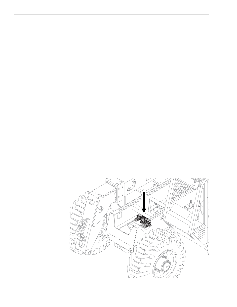
Mid-Inlet Control Valve
Description
6K-37 (S/N 318–)
6K-42 (S/N 120–)
8K-42 (S/N 221–)
10K-42 (S/N 107–)
10K-54 (S/N 104–)
644B-37 (S/N 591, 667–)
644B-42 (S/N 208–)
844C-42 (S/N 622–)
1044C-42 (S/N 117–)
1044C-54 (S/N 155–)
Fig. 5-49: Mid-Inlet Control Valve Location
0
80
6 0
4 0
2 0
- 2 0
K
1140