Lull 6K Service Manual User Manual
Page 294
Boom and Transfer
6-44
Service Manual — Models 644B, 6K, 844C, 8K, 1044C, 10K
Removal
Selector Valve (Mid-Inlet
System)
644B-37 (S/N 591, 667–)
644B-42 (S/N 208–)
6K-37 (S/N 318–)
6K-42 (S/N 120–)
844C-42 (S/N 622–)
8K-42 (S/N 221–)
1044C-42 (S/N 117–)
1044C-54 (S/N 155–)
10K-42 (S/N 107–)
10K-54 (S/N 104–)
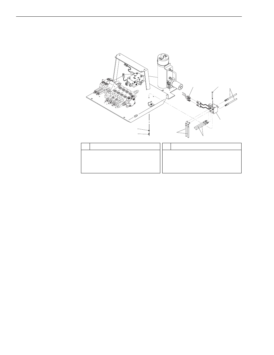
Fig. 6-27: Selector Valve Installation – Models with Mid-Inlet Hydraulics
(Ref. Fig. 6-27) The following steps are required to remove the selector
valve in models with a mid-inlet hydraulic system.
1. Follow preparation procedures as outlined in Section 3 of this manual.
2. Install brake pressure diagnostic port test gauge into brake diagnostic
port.
3. While watching test gauge, press and release brake pedal numerous
times until pressure gauge reads 0 psi. Remove test gauge from
diagnostic port.
4. For 644B, 844C, and 1044C models, remove roll-back hose tray.
5. To avoid contamination of the system, clean selector valve.
6. Disconnect joystick wiring harness (Item 8) from selector valve.
7. Tag and loosen six (6) hydraulic hoses (Items 3, 4, and 6) and bleed
any remaining oil into a suitable container. Disconnect hoses. Cap
fittings and hoses.
8. Remove two (2) each nuts (Item 1), lockwashers (Item 2), and
capscrews (Item 7) securing selector valve (Item 5) to the valve plate.
9. Take selector valve and mounting hardware to a suitable area for
cleaning and further disassembly.
10. Clean mounting hardware with solvent. Dry with compressed air,
inspect for damage, and replace as necessary.
#
Description
1
Lockwasher
2
Nut
3
Hydraulic Hoses
4
Hydraulic Hoses
#
Description
5
Selector Valve
6
Hydraulic Hoses (Joystick)
7
Capscrew
8
Joystick Wiring Harness
1
J1
1
8
2
2
3
8
7
6
5
4