Lull 6K Service Manual User Manual
Page 461
Boom and Transfer
Service Manual — Models 644B, 6K, 844C, 8K, 1044C, 10K
6-211
3. Secure cylinder to outer boom section with hardware as follows.
For Models 1044C-54 (S/N 101–143) and 10K-54 (S/N 101–103)
(See View A):
Use two (2) each flatwashers (Item 17), lockwashers (Item 16), and
capscrews (Item 15). Torque capscrews to 200 ft-lbs.
For Models 1044C-54 (S/N 144–) and 10K-54 (S/N 104–):
Use two (2) each nuts (Item 14), flatwashers (Item 8), and capscrews
(Item 7). Install as many shims (Items 12 and 13) as necessary before
installing the nuts. Torque nuts to 680 ft-lbs.
4. Torque rod nut to 733 ft-lbs.
5. If socket setscrews (Item 2) were removed, install them in rod nut.
6. Reconnect two (2) hydraulic tubes (Item 10) to elbows on extension
cylinder. Torque tube swivel nuts to 79–88 ft-lbs.
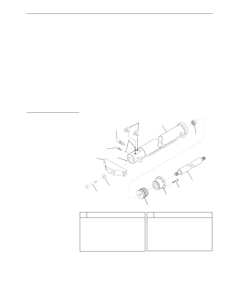
Overhaul, Extension Cylinder
Fig. 6-226: 4-Section Boom Extension Cylinder Assembly
(Ref. Fig. 6-226) The following steps are required to overhaul the boom
extension cylinder.
J
113
4
#
Description
1
Bolt
2
Flatwasher
3
Extension Cylinder Base Mount
4
Hollow Hex O-ring Plug
5
Counterbalance Valve Cartridge
6
Counterbalance Valve Cartridge
7
90° O-ring Elbow
#
Description
8
Cylinder Barrel
9
Rod Nut
10 Piston
11 Rod Bearing Head
12 Capscrew
13 Cylinder Rod
5
4
9
6
7
8
13
12
11
10
4
1
2
3