Lull 6K Service Manual User Manual
Page 204
Supply, Pressure, and Return Hydraulics
5-60
Service Manual — Models 644B, 6K, 844C, 8K, 1044C, 10K
Assembly, Inlet Cover
(Ref. Fig. 5-37) The following procedure describes reassembly of the inlet
cover.
1. Lubricate threaded portion, including the O-ring, on each fitting and
plug with hydraulic oil before installing them.
2. Install hollow plug (Item 7) and hex plug (Item 8) on inlet cover. Torque
each to 105–115 ft-lbs.
3. Install diagnostic plug (Item 6) on hollow plug and torque to 205–235
in-lbs.
4. Install connector (Item 11) on inlet cover. Torque connector to 105–115
ft-lbs.
5. Install elbow (Item 10) on inlet cover. Be sure elbow is installed in
same position as shown in Fig. 5-37. Torque elbow to 75–85 ft-lbs.
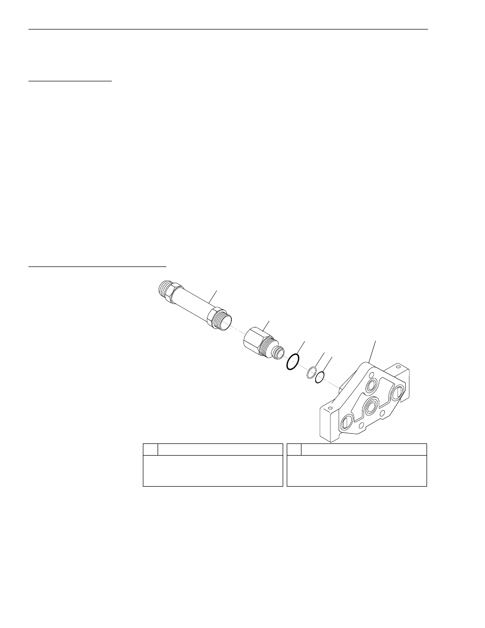
Disassembly, Power-Beyond Sleeve
Fig. 5-38: Power-Beyond Sleeve Assembly
(Ref. Fig. 5-38) The following steps are required to disassemble the
power-beyond sleeve.
1. Loosen and remove long connector (Item 1) from power-beyond sleeve
(Item 2).
2. Loosen and remove power-beyond sleeve from cover housing (Item 6).
1
2
3
4
5
6
K
1072
#
Description
1
Long O-Ring Connector
2
Power-Beyond Sleeve
3
O-Ring
#
Description
4
Backup Ring
5
O-Ring
6
Cover Housing