Rear axle stabilizer control valve, Installation, Description – Lull 6K Service Manual User Manual
Page 229
Supply, Pressure, and Return Hydraulics
Service Manual — Models 644B, 6K, 844C, 8K, 1044C, 10K
5-85
Installation
Mid-Inlet Control Valve
1. (Ref. Fig. 5-53) Position the control valve on the valve plate. Secure
with three (3) lockwashers and capscrews.
2. Connect all hydraulic hoses and tubes to fittings on the control valve.
Torque per instructions in Section 3.
3. Start the engine and repeatedly cycle all hydraulic circuits controlled by
the valve to remove air from the system.
4. Stop engine and check for hydraulic leaks. Tighten connections as
necessary.
Rear Axle Stabilizer Control Valve
Description
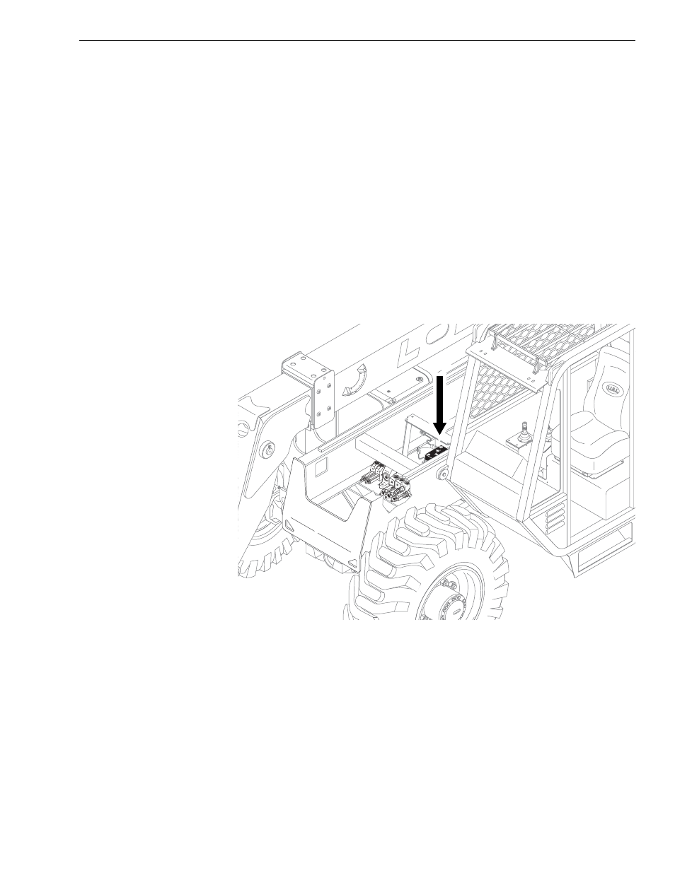
Fig. 5-54: Rear Axle Stabilizer Control Valve Location
(Ref. Fig. 5-54) The rear axle stabilizer control valve is located on the valve
plate near the middle of the machine. This valve controls hydraulic
functions using the following valves:
• Solenoid Valve
• Piloted 3-Way Cartridge Valve
• Sequence Cartridge Valve
• Piloted 2-Way Cartridge Valve
• Shuttle Cartridge Valve
• Boom Extend Lockout Valve - Used on models with outriggers
(Standard equipment on 10K-54 and 1044C-54)
0
80
6 0
4 0
2 0
- 2 0
K
1
153