Lull 6K Service Manual User Manual
Page 133
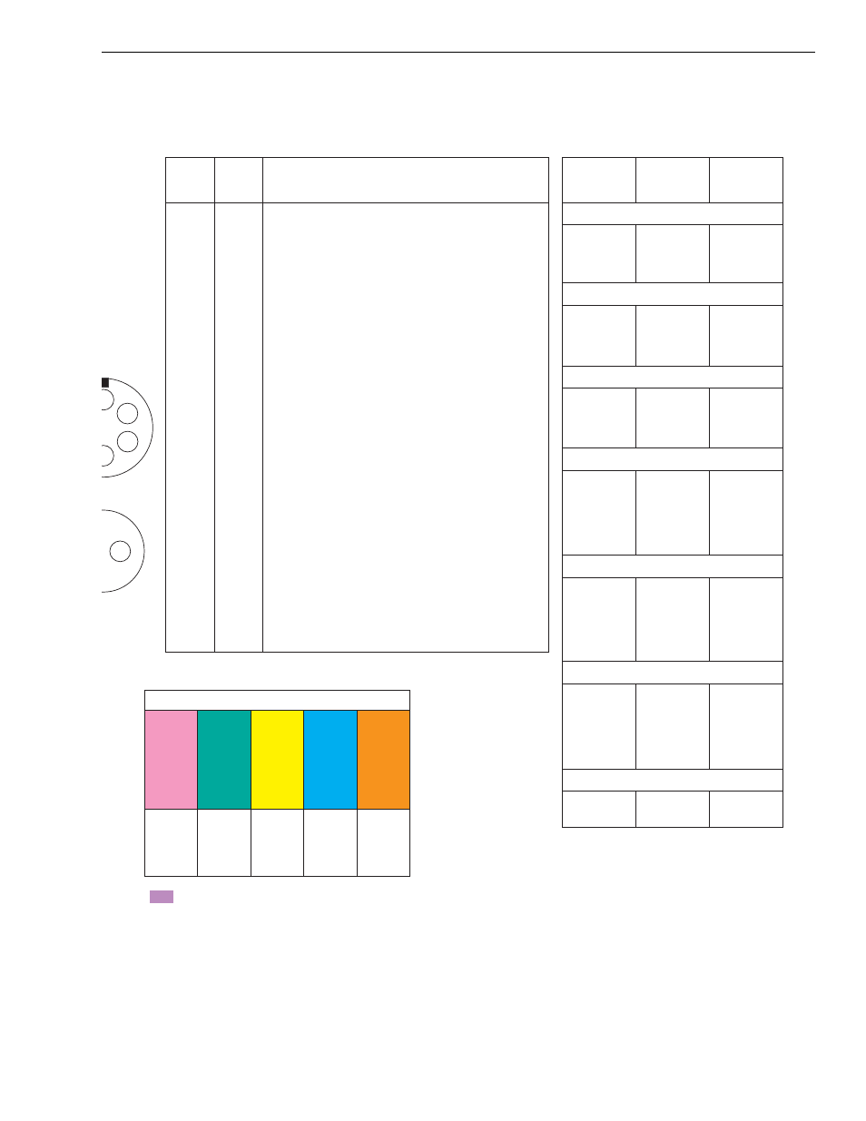
Reference Diagrams
Service Manual — Models 644B, 6K, 844C, 8K, 1044C, 10K
4-46
F
A
D
E
mission
onnector
Sensor
nector
604
608
652
654
682
Wire Groups Having Common Wires
450
620
624
648
666
678
658
508
588
662
532
592
674
512
584
(+)
Pin 1, 2
(–)
Pin 18,
35
Pin 5
Reverse
Circuit
Pin 24
N/A
Pin 29
Neutral
Start
Circuit
N/A = Wires Not Applicable
Harness
Connector
Location
Harness
Wire
Number
EST-19
Connector
Location
Shifter Plug Female Pins
A
500
Pin
19
B
504
Pin
23
C
508
Pin
5
D
512
Pin
29
Shifter Plug Male Pins
A
520
Pin
25
B
524
Pin
8
C
528
Pin
26
D
532
Pin
24
Diagnostic Plug
A
640
Pin
21
B
C
648
Pin
18,
35
D
652
Pin
1,
2
Vehicle Harness Plug Female Pins
A
580
Pin
11
B
584
Pin
29
C
588
Pin
5
D
592
Pin
24
E
596
Pin
22
F
600
Pin
12
Vehicle Harness Plug Male Pins
A
604
Pin
1,
2
B
608
Pin
1,
2
C
612
Pin
13
D
616
Pin
30
E
620
Pin
18,
35
F
624
Pin
18,
35
Transmission Valve Connector Female Pins
A
430
Pin
31
B
434
Pin
33
C
438
Pin
15
D
442
Pin
32
E
446
Pin
14
F
450
Pin
18,
35
Speed Sensor Connector Female Pins
1
460
Pin
27
2
464
Pin
17
1.
682
Power In — In common with wires 604, 608, 652, and 654
2.
654
Power In — In common with wires 604, 608, 652, and 682
3.
4.
5.
658
To shifter Pink wire and backup alarm relay — In
common with wires 508 and 588
6.
7.
8.
524
To shifter Green wire
9.
10.
11.
580
N/A — Designated for speedometer
12.
600
N/A — Designated for kickdown light
13.
612
N/A — Designated for operating indicator
14.
446
To M4 solenoid
15.
438
To M2 solenoid
16.
17.
464
To speed sensor
18.
666
Ground — In common with wires 450, 620, 624, 648, and 678
19.
500
To shifter Red wire
20.
21.
640
N/A — To diagnostic plug
22.
596
Clutch cutoff
23.
504
To shifter Yellow wire
24.
662
N/A — Shifter Violet wire — In common with wires 532 and 592
25.
520
To shifter Black wire
26.
528
To shifter Blue wire
27.
460
To speed sensor
28.
29.
674
To shifter Gray wire and neutral start relay — In common
with wires 512 and 584
30.
616
N/A — Designated for relay option
31.
430
To M5 solenoid
32.
442
To M3 solenoid
33.
434
To M1 solenoid
34.
35.
678
Ground — In common with wires 450, 620, 624, 648, and 666
EST-19
Plug Pin
Position
Harness
Wire
Number
Description
Electrical Diagram, ZF DW-2/EST-19 System Harness - Diagram 12