Lull 6K Service Manual User Manual
Page 447
Boom and Transfer
Service Manual — Models 644B, 6K, 844C, 8K, 1044C, 10K
6-197
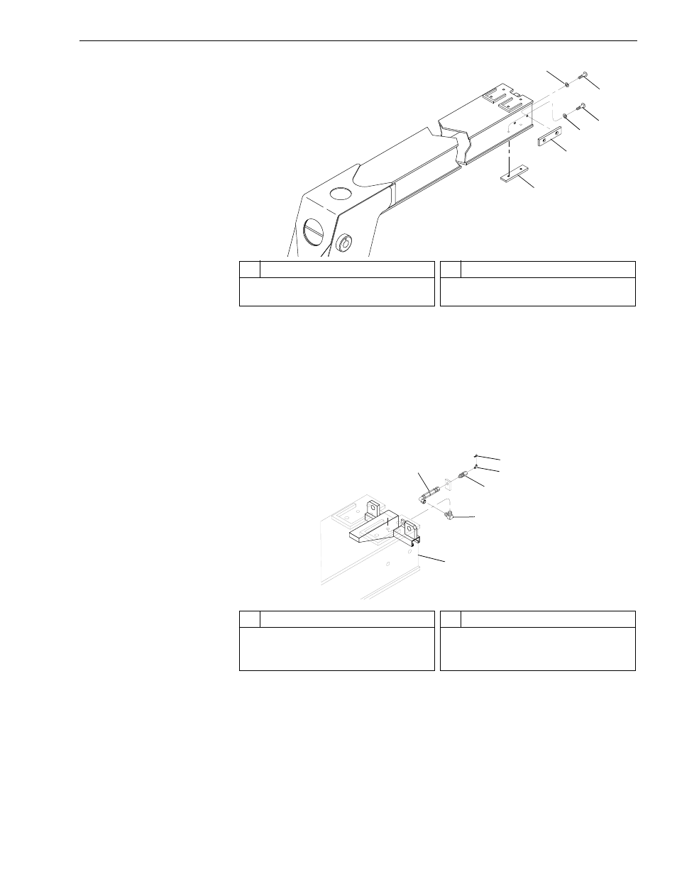
Fig. 6-210: Slide Pad Installation – Inner Boom Section
26. (Ref. Fig. 6-210) After applying thread locking compound to the
capscrews, install two (2) lower and two (2) side slide pads (Items 1
and 2) on inner boom section according to drawing specifications with
lockwashers (Item 3) and capscrews (Item 4). Torque capscrews to
180 in-lbs.
Fig. 6-211: Grease Hose Installation
27. (Ref. Fig. 6-211) Install grease hose assembly on rear of inner boom
section as follows:
a. Install two (2) elbows (Item 3) on inside of inner boom section
making sure elbows are in correct position for grease hose to be
connected.
J
1
247
1
2
3
4
4
3
#
Description
1
Lower Slide Pad
2
Side Slide Pad
#
Description
3
Lockwasher
4
Button-Head Socket Capscrew
J
123
5
3
5
1
4
6
2
#
Description
1
Grease Hose
2
Inner Boom Section
3
Elbow
#
Description
4
Bulkhead Adapter
5
Grease Fitting
6
Grease Fitting Cover