Lull 6K Service Manual User Manual
Page 206
Supply, Pressure, and Return Hydraulics
5-62
Service Manual — Models 644B, 6K, 844C, 8K, 1044C, 10K
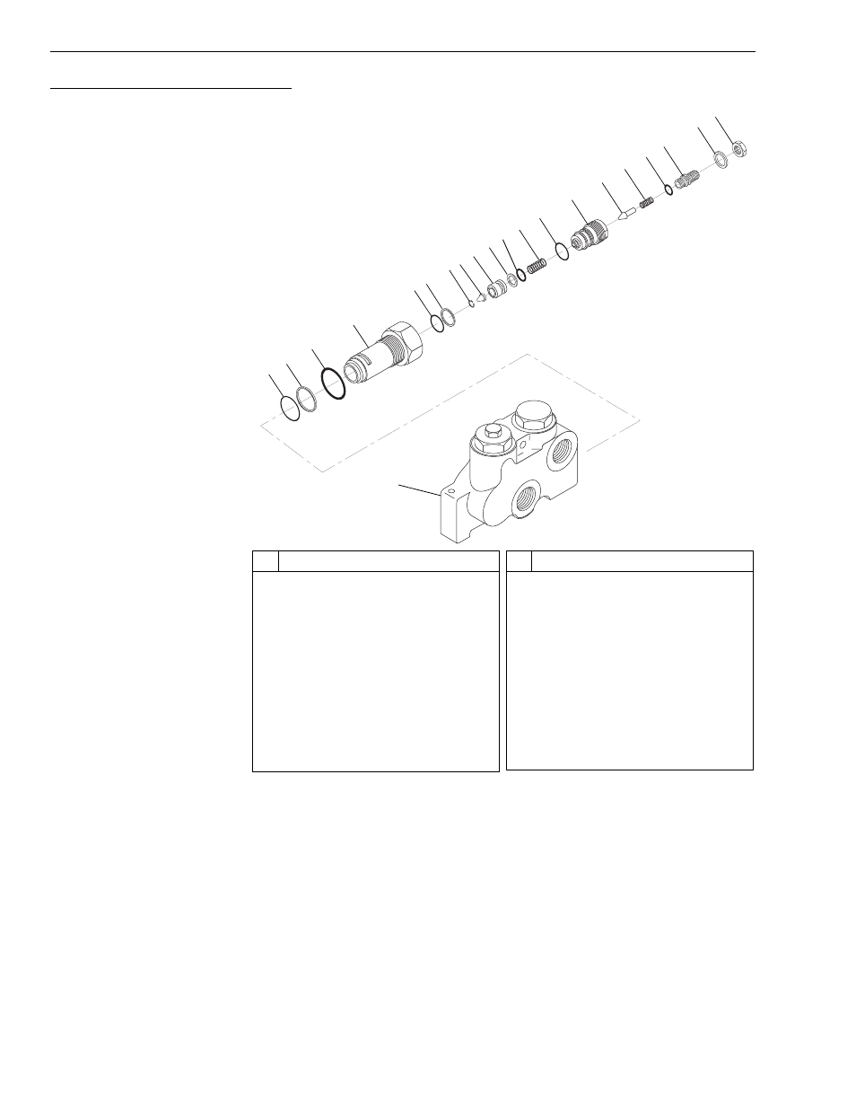
Disassembly, Main Relief Assembly
Fig. 5-39: Main Relief Valve
(Ref. Fig. 5-39) The following steps are required to disassemble the main
relief.
1. Loosen and remove main relief valve (Items 3 thru 20) from cover
assembly (Item 21).
2. Remove backup ring (Item 2) and O-ring (Item 1) from cover assembly.
3. Loosen and remove jam nut (Item 20) and washer (Item 19) from pilot
assembly body (Item 14).
4. Loosen and remove adjustment screw (Item 18) from pilot assembly
body.
K
1073
#
Description
1
O-Ring
2
Backup Ring
3
O-Ring
4
Relief Valve Body
5
O-Ring
6
Backup Ring
7
Retaining Ring
8
Filter
9
Main Poppet
10 Backup Ring
11 O-Ring
#
Description
12 Spring
13 O-Ring
14 Pilot Assembly Body
15 Relief Poppet
16 Pilot Spring
17 O-Ring
18 Adjustment Screw
19 Washer
20 Jam Nut
21 Cover Assembly
1
2
3
4
5
21
6
7
8
9
10
11
12
13
14
15
16
17
18
19
20