Lull 6K Service Manual User Manual
Page 253
Boom and Transfer
Service Manual — Models 644B, 6K, 844C, 8K, 1044C, 10K
6-3
Removal
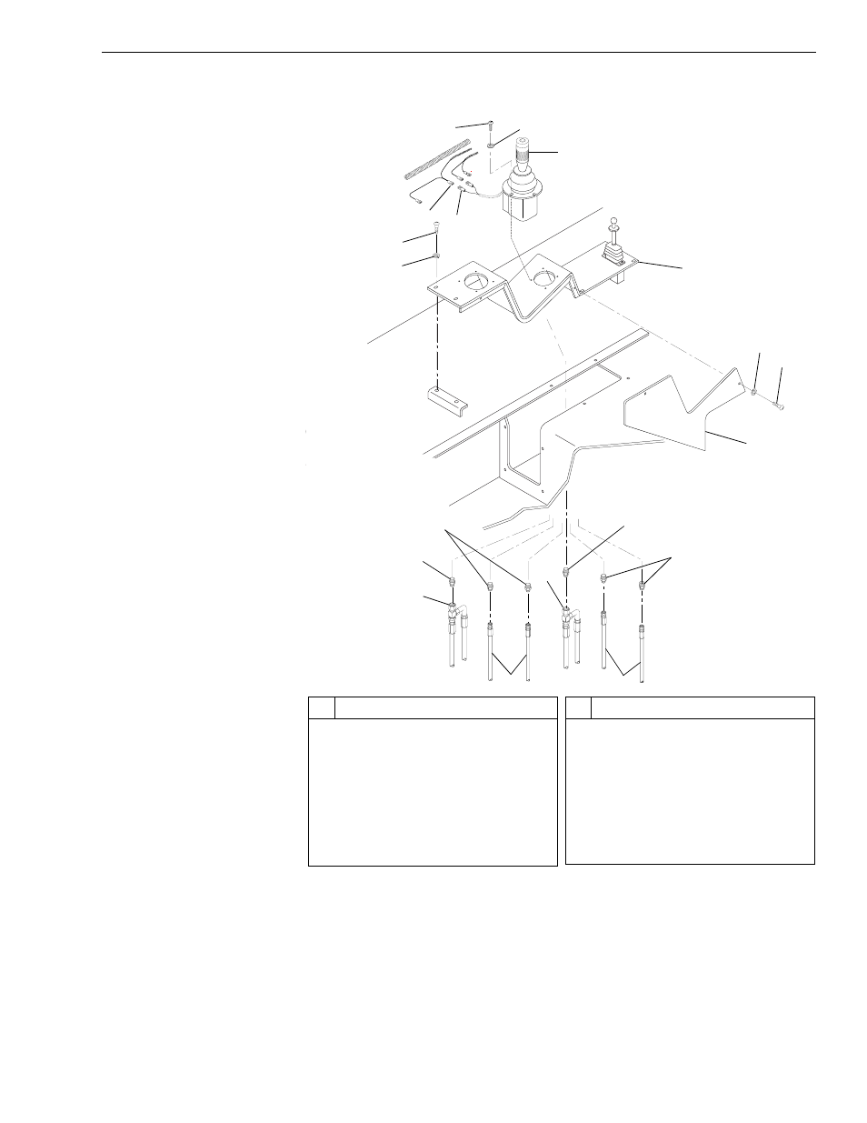
Joystick
Fig. 6-3: Joystick Installation
(Ref. Fig. 6-3) The following steps are required to remove the joystick.
1. Follow preparation procedures as outlined in Section 3 of this manual.
2. Remove two (2) capscrews (Item 14) and lockwashers (Item 15)
securing side panel (Item 13) to control panel (Item 8). Remove side
panel.
J
1120
#
Description
1
Button Head Socket Capscrew
2
Lockwasher with Internal Teeth
3
Phillips Truss Head Screw
4
Flatwasher
5
Wiring Harness
6
Lead Connector
7
Joystick
8
Control Panel
#
Description
9
Connector
10 Connector
11 Swivel Tee
12 Hydraulic Hose
13 Side Panel
14 Capscrew
15 Lockwasher
3
5
4
6
1
2
7
8
14
15
13
9
10
11
12
12
9
10
11
This manual is related to the following products: