Lull 6K Service Manual User Manual
Page 407
Boom and Transfer
Service Manual — Models 644B, 6K, 844C, 8K, 1044C, 10K
6-157
CAUTION: Make sure each cylinder is fully supported so it does not fall
and cause personal or equipment damage when it is being
removed.
12. (Ref. Fig. 6-170) Starting at a rear carriage tilt cylinder (Item 6), use a
slide hammer puller threaded into the pivot pin (Item 4) to remove the
pivot pin from boom. After the pivot pin has been removed, allow the
cylinder to swing down and away from the boom.
CAUTION: Use suitable blocking to support cylinders and prevent
damage to the surrounding structure.
13. (Ref. Fig. 6-170) Repeat Step 24 for the remaining rear carriage tilt
cylinder.
14. (Ref. Fig. 6-170) Continue with each of the two (2) hoist cylinders
(Item 7) by using a slide hammer puller threaded into pivot pin (Item 5)
to remove it. After the pivot pin has been removed, allow the cylinder to
swing down and away from the boom.
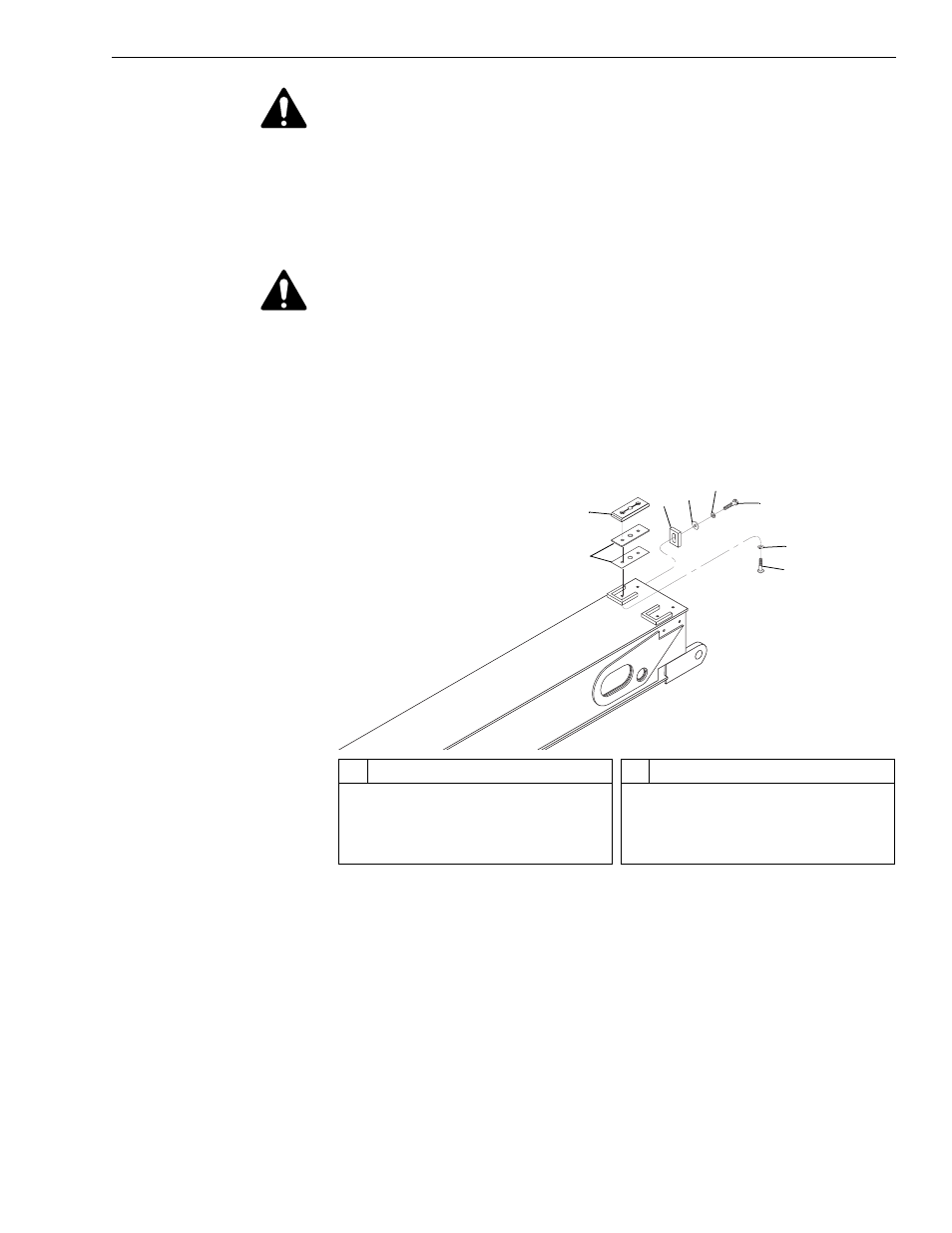
Fig. 6-171: Upper Rear Slide Pad Removal – Middle (Rear) Boom Section
15. (Ref. Fig. 6-171) Remove upper rear slide pads from middle (rear)
boom section as follows:
a. Remove two (2) each capscrews (Item 6), lockwashers (Item 5),
flatwashers (Item 4), and pad retainers (Item 3) from rear of middle
(rear) boom section.
b. Remove four (4) capscrews (Item 8) and lockwashers (Item 7)
securing upper slide pads to rear of middle (rear) boom section.
Remove two (2) slide pads (Item 2) and shims (Item 1).
J
1270
8
7
2
1
5
6
4
3
#
Description
1
Shim
2
Upper Rear Slide Pad
3
Pad Retainer
4
Flatwasher
#
Description
5
Lockwasher
6
Capscrew
7
Lockwasher
8
Button-Head Socket Capscrew