Lull 6K Service Manual User Manual
Page 543
Frame Tilt and Oscillation
Service Manual — Models 644B, 6K, 844C, 8K, 1044C, 10K
7-41
Installation
Frame Tilt Lockout Valve
(Ref. Fig. 7-24) The following procedure describes installation of the frame
tilt lockout valve.
1. Position frame tilt lockout valve (Item 3) on mounting bracket (Item 7)
and secure with two (2) capscrews (Item 2), lockwashers (Item 8), and
nuts (Item 9). Torque nuts to 50 in-lbs.
2. Position mounting bracket on valve plate. Secure with two (2)
flatwashers (Item 6), lockwashers (Item 5), and capscrews (Item 4).
Torque capscrews to 156 in-lbs.
3. Connect electrical leads (Item 1).
4. Connect two (2) hydraulic hoses (Item 11) to connectors (Item 12).
Torque nuts to 130–150 in-lbs.
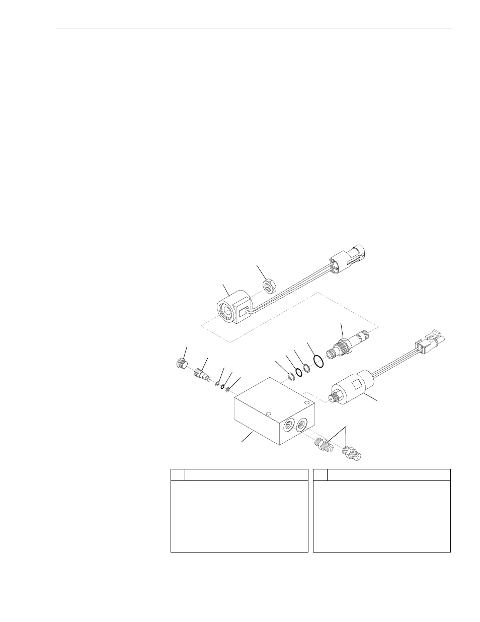
Overhaul
Frame Tilt Lockout Valve
Fig. 7-25: Frame Tilt Lockout Valve (Exploded View)
#
Description
1
Solenoid Coil
2
Nut
3
Solenoid Valve
4
O-Ring
5
Backup Ring
6
O-Ring
7
Frame Tilt Override Press. Switch
#
Description
8
O-Ring Fittings
9
Valve Body
10 Backup Ring
11 O-Ring
12 Shuttle Valve
13 Plug, O-Ring
1
2
3
4
5
6
5
7
8
9
10
11
12
10
13