E1013 – Lull 6K Service Manual User Manual
Page 557
Transmission
Service Manual — Models 644B, 6K, 844C, 8K, 1044C, 10K
8-9
3. Because the proximity switch can also declutch the transmission, the
boom elevation must be lower than 40°.
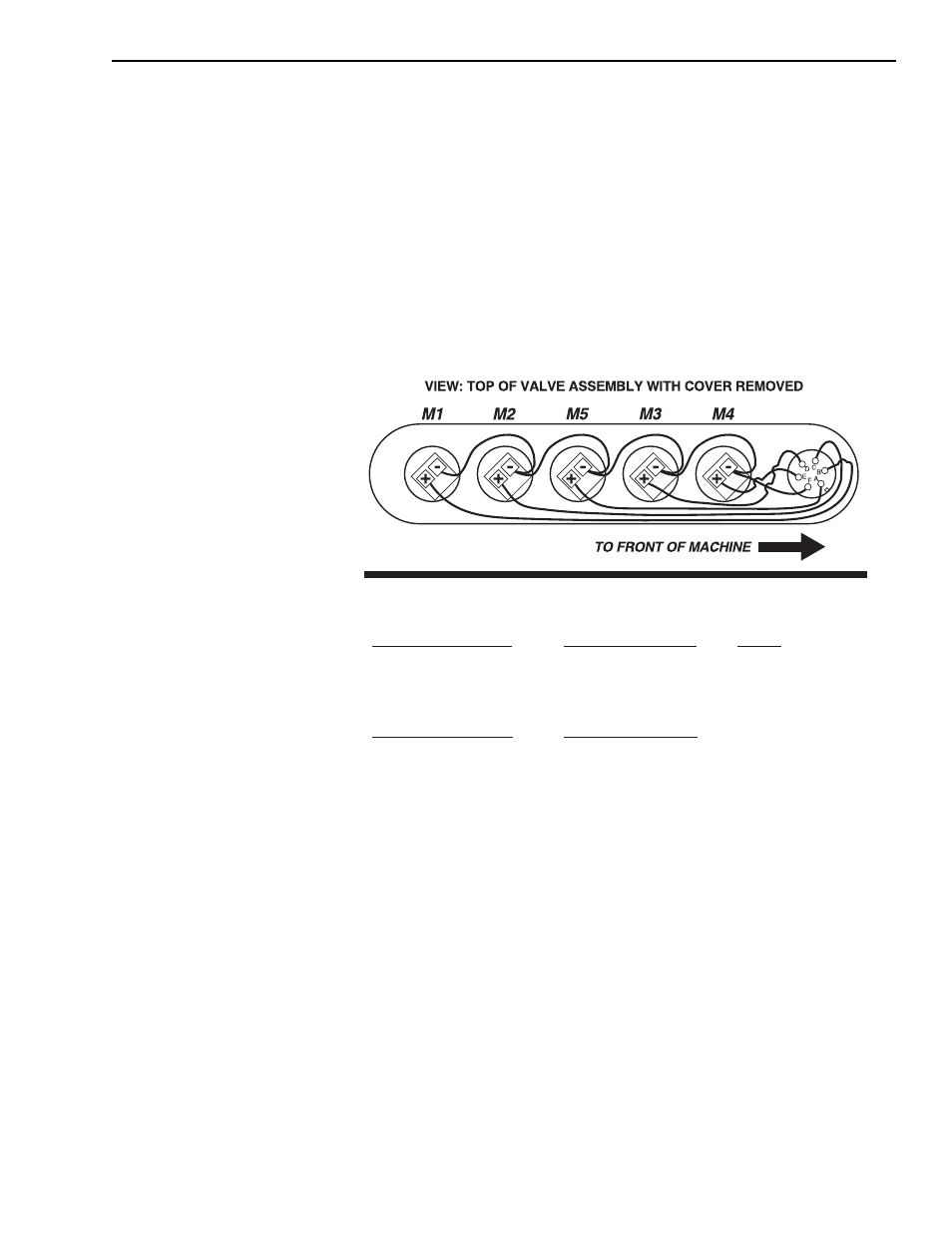
4. Remove cover at transmission valve to gain access to solenoids.
5. Turn ignition to “ON” position.
6. Wait five seconds before shifting. This allows the EST-19 to perform
self-diagnostic testing.
7. Select direction and speed range.
8. Probe positive (+) contacts for voltage.
9. Test all direction and speed range combinations shown in Fig. 8-3.
10. If any discrepancies are found, contact the JLG Service Department.
Fig. 8-3: DW-2 Controller Signal Combinations Measured at Valve
Solenoids
Inductive Sensor Test
Inductive sensor failure can be detected in two ways.
1. Electronically by the microprocessor
2. Irregular transmission operation
Irregular transmission operation is an indication of an inductive sensor
fault. The symptoms are:
1. When in forward gear, downshifts from 4th-to-3rd-to-2nd-to-1st are
allowed but no up-shifts back to 2nd, 3rd, or 4th gear are possible.
2. When in reverse gear, downshifts from 3rd-to-2nd-to-1st are allowed
but no upshifts back to 2nd or 3rd gear are possible.
Forward, Declutch OFF
1
st
Gear — M3 M2 M4
2
nd
Gear — M3 M4
3
rd
Gear — M3
4
th
Gear — M5
Reverse, Declutch OFF
1
st
Gear — M1 M2 M4
2
nd
Gear — M1 M4
3
rd
Gear — M1
Forward. Declutch ON
1
st
Gear — M2 M4
2
nd
Gear — M4
3
rd
Gear — —
4
th
Gear — —
WG-100, 3- OR 4-SPEED TRANSMISSION SOLENOID CONFIGURATION
DW-2 CONTROLLER SIGNALS MEASURED AT VALVE SOLENOIDS
Neutral
1
st
Gear — —
2
nd
Gear — —
3
rd
Gear — —
4
th
Gear — —
Reverse, Declutch ON
1
st
Gear — M2 M4
2
nd
Gear — M4
3
rd
Gear — —
E1013