Lull 6K Service Manual User Manual
Page 289
Boom and Transfer
Service Manual — Models 644B, 6K, 844C, 8K, 1044C, 10K
6-39
Removal
Selector Valve (Control
Manifold System)
644B-37 (S/N 101–590, 592–666)
644B-42 (S/N 101–207)
6K-37 (S/N 101–317)
6K-42 (S/N 101–119)
844C-42 (S/N 101–621)
8K-42 (S/N 101–220)
1044C-42 (S/N 101–116)
1044C-54 (S/N 101–154)
10K-42 (S/N 101–106)
10K-54 (S/N 101–103)
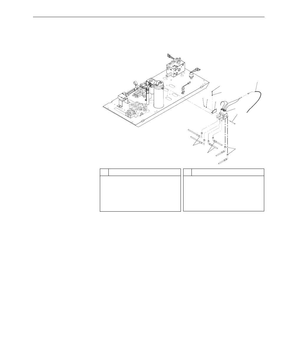
Fig. 6-24: Selector Valve Installation – Models with Control Manifold
Hydraulics
(Ref. Fig. 6-24) The following steps are required to remove the selector
valve in models with a control manifold hydraulic system.
1. Follow preparation procedures as outlined in Section 3 of this manual.
2. Install brake pressure diagnostic port test gauge into brake diagnostic
port.
3. While watching test gauge, press and release the brake pedal
numerous times until pressure gauge reads 0 psi. Remove test gauge
from diagnostic port.
4. For 644B, 844C, and 1044C models, remove rollback hose tray.
5. To avoid contamination of the system, clean selector valve.
6. Disconnect joystick wiring harness (Item 11) from selector valve.
7. Tag and loosen six (6) hydraulic hoses (Items 1, 2 and 3) and bleed
any remaining oil into a suitable container. Disconnect hoses. Cap
fittings and hoses.
#
Description
1
Hydraulic Hose
2
Hydraulic Hose (Joystick)
3
Hydraulic Hose
4
Capscrew
5
Selector Valve
6
Mounting Bracket
#
Description
7
Lockwasher
8
Nut
9
Lockwasher
10 Capscrew
11 Joystick Wire Harness
1
J
1179
2
3
4
5
6
8 7
9
10
11