Lull 6K Service Manual User Manual
Page 295
Boom and Transfer
Service Manual — Models 644B, 6K, 844C, 8K, 1044C, 10K
6-45
Installation
Selector Valve (Mid-Inlet
System)
644B-37 (S/N 591, 667–)
644B-42 (S/N 208–)
6K-37 (S/N 318–)
6K-42 (S/N 120–)
844C-42 (S/N 622–)
8K-42 (S/N 221–)
1044C-42 (S/N 117–)
1044C-54 (S/N 155–)
10K-42 (S/N 107–)
10K-54 (S/N 104–)
(Ref. Fig. 6-27) The following steps are required to install the selector
valve in models with a mid-inlet hydraulic system.
1. Secured the selector valve (Item 5) to the valve plate with two (2) each
capscrews (Item 7), lockwashers (Item 2), and nuts (Item 1). Torque
nuts to 50 in-lbs.
2. Reconnect four (4) hydraulic hoses (Items 3 and 6) to respective
elbows at ports A3, B3, P1, and P2 on selector valve. Torque hydraulic
hose swivel nuts to 130–150 in-lbs.
3. Install two (2) hydraulic hoses (Item 4) to ports A1 and B1 on selector
valve and torque hose swivel nuts to 130–150 in-lbs.
4. Reconnect joystick wiring harness (Item 8) to selector valve.
Overhaul
Selector Valve (Mid-Inlet
System)
644B-37 (S/N 591, 667–)
644B-42 (S/N 208–)
6K-37 (S/N 318–)
6K-42 (S/N 120–)
844C-42 (S/N 622–)
8K-42 (S/N 221–)
1044C-42 (S/N 117–)
1044C-54 (S/N 155–)
10K-42 (S/N 107–)
10K-54 (S/N 104–)
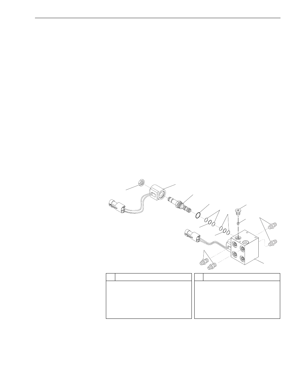
Fig. 6-28: Selector Valve Assembly – Models with Mid-Inlet Hydraulics
(Ref. Fig. 6-28) The following steps describe disassembly and overhaul of
the selector valve assembly in models with a mid-inlet hydraulic system.
#
Description
1
Nut
2
Coil
3
Solenoid Valve
4
O-ring
5
Backup Rings
6
O-ring
#
Description
7
Backup Rings
8
O-ring
9
Connector
10 Valve Body
11 Orifice
12 O-ring Plug
1
J
1183
2
3
4
5
7
6
9
12
11
9
10
8