Reservoir breather – Lull 6K Service Manual User Manual
Page 171
Supply, Pressure, and Return Hydraulics
Service Manual — Models 644B, 6K, 844C, 8K, 1044C, 10K
5-27
6. Remove the diffuser (Item 7) and clean with solvent. Dry with
compressed air.
Installation
Return Filter Assembly
(Ref. Fig. 5-17) The following procedures describes installation of the
return filter assembly.
1. Reassemble the diffuser (Item 7) and the rubber gasket (Item 8) with
the hydraulic return assembly (Item 6).
2. Install the return filter assembly on the hydraulic reservoir with the four
(4) lockwashers (Item 2) and capscrews (Item 3). Torque the
capscrews evenly to 276 in-lbs.
3. Connect the return manifold tube (Item 4) to the connector (Item 5) on
the hydraulic oil return filter assembly (Item 6). Torque the nut on the
return manifold tube to 188–213 ft-lbs.
Reservoir Breather
Description
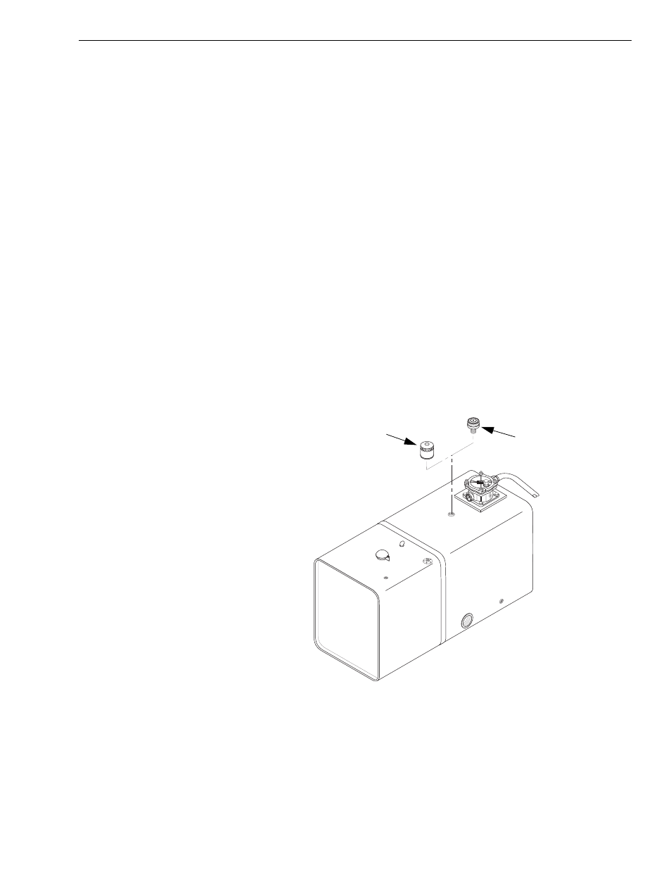
Fig. 5-18: Reservoir Breather
(Ref. Fig. 5-18) The reservoir breather is located on the top of the
hydraulic reservoir near the return filter. It allows for expansion of fluid and
prevents vacuum in the tank.
K
1096
Models with
Models with Control
Manifold Hydraulics
Mid-Inlet Hydraulics