Theory of operation and circuit logic – Lull 6K Service Manual User Manual
Page 521
Frame Tilt and Oscillation
Service Manual — Models 644B, 6K, 844C, 8K, 1044C, 10K
7-19
Theory of Operation and Circuit Logic
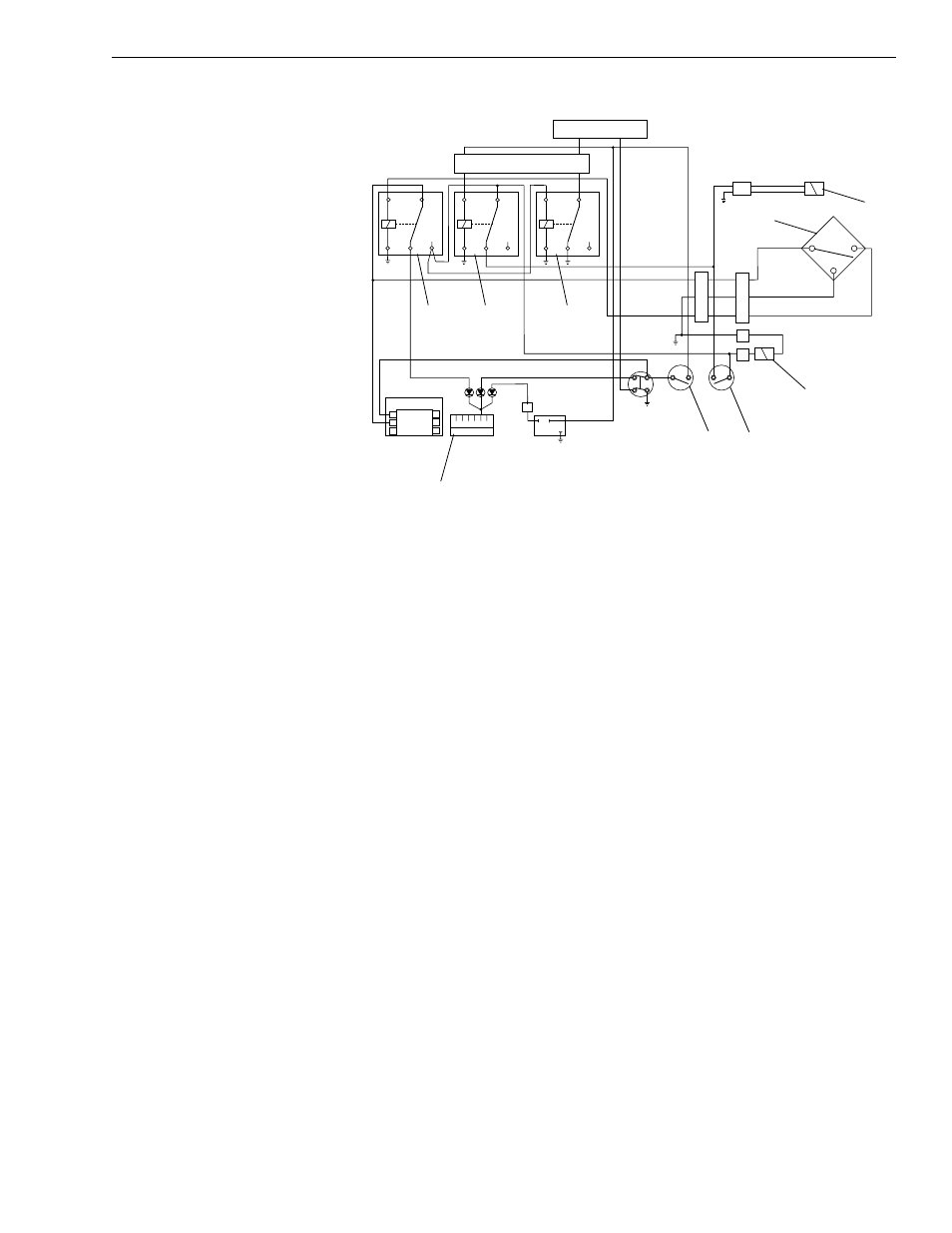
Fig. 7-12: Rear Oscillation Lock Component Locations
(Reference Fig. 7-12 and Section 4, “Reference Diagrams”) Major
components of the rear oscillation lock system are:
1. Boom Elevation Proximity Switch (S1) — senses boom position.
2. Proximity Switch Relay (R1) — receives signal from the proximity
switch (S1).
3. Electronic Control Unit (ECU) (Transmission) — controls transmission
directional and gearshift functions.
4. Service Brake Pressure Switch (S2) — senses pressure in service
brake circuit (brakes applied).
5. Service Brake Relay (R2) — receives signal from the service brake
pressure switch (S2).
6. Solenoid Valve (V1) — mounted on oscillation control block at the rear
oscillation lock cylinder. This component locks/unlocks the cylinder.
See “Oscillation Control Block” on page 7-31.
7. Frame Tilt Lockout Solenoid Valve (V2) — enables/disables frame tilt
functions.
8. Frame Tilt Override Switch (S3) — senses pilot pressure directed to
the frame tilt valve section. Directs power to solenoid valve (V1), which
unlocks the rear oscillation lock cylinder.
9. REAR OSC LOCK Light Relay (R3) — receives signal from the
proximity switch relay (R1).
J
126
0
Dash Panel
ECU
R1
R2
R3
S2
S3
S1
V2
V1
B
1
C
Parking
Pressure
Brake
Switch
Fuse
Panel
Transmission
Disconnect
Switch
B
A
C
B
A
2
3
6
5
4
A B C D E F
D
2
3
7
+
+
–
–
A
B
C
Solenoid
Valve On
Stabilizer
Block
B
A
2
5
9
3
4
8
7
1
6
6 Pole
W/P
Conn.