Lull 6K Service Manual User Manual
Page 517
Frame Tilt and Oscillation
Service Manual — Models 644B, 6K, 844C, 8K, 1044C, 10K
7-15
2. Install new bushings so they are flush with outer edge boss to 0.02"
below. For machines with lower (rod end) pivot bushing installed in
front axle: Install bushing so that it is centered in axle boss.
Assembly, Frame Tilt Cylinder
1. (Ref. Fig. 7-7) Install two (2) orifices (Item 5) using a large, flat bladed
screw driver.
2. Install two (2) O-ring plugs (Item 4) and torque to 125–145 in-lbs.
3. Lubricate new O-ring with hydraulic oil and install inside piston (seals
rod to piston).
4. Lubricate new O-ring, backup ring, seals, and wear rings with hydraulic
oil and install on head (Item 12). Using a seal driver, install new wiper
seal in head. Lubricate wiper seal with hydraulic oil.
5. Slide head (Item 12), stroke limiter (Item 8) and piston (Item 9) onto
rod (Item 11). Lubricate threads on rod with hydraulic oil and install rod
nut (Item 10). Torque rod nut to 850 ft-lbs.
6. Lubricate new seal and wear rings with hydraulic oil and install on
piston.
7. (Ref. Fig. 7-7) Lubricate threads on capscrews (Item 13) with hydraulic
oil. Coat inside of barrel (Item 2) with hydraulic oil. Carefully insert rod
and head into barrel. Do not damage seals during assembly. Install
and snug capscrews (Item 13). Do not torque capscrews (instructions
follow).
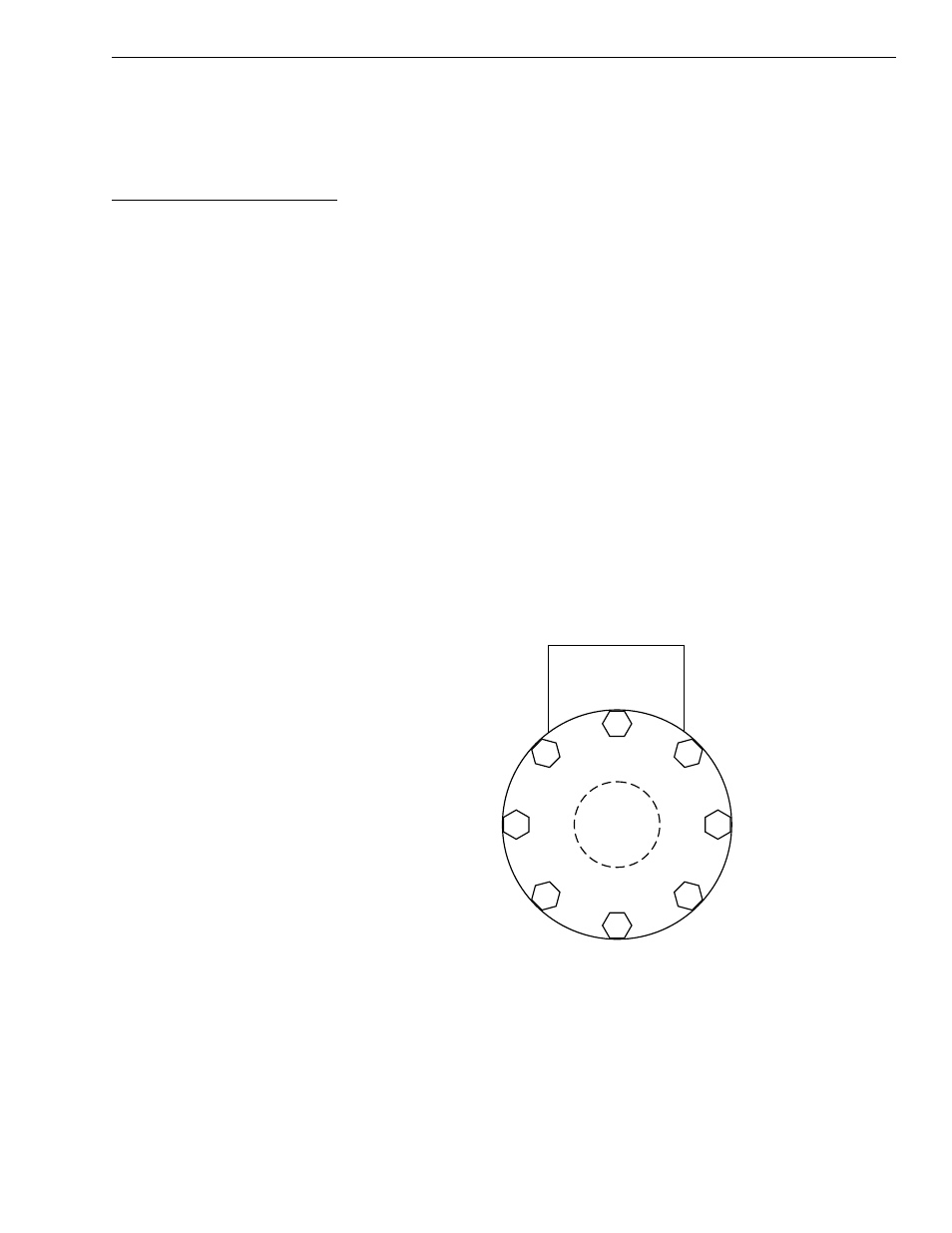
Fig. 7-8: Head Capscrew Torque Sequence
8. Following sequence shown in Fig. 7-8, torque capscrews to an initial
value of 30 ft-lbs. Follow sequence again and torque capscrews to a
final value of 65 ft-lbs.
9. Install two (2) O-ring fittings (Item 6) and torque to 46–50 ft-lbs.
10. Install two (2) swivel fittings (Item 7) and torque nuts to 235–265 in-lbs.
1
2
3
4
5
6
7
8
K
1024