Lull 6K Service Manual User Manual
Page 486
Boom and Transfer
6-236
Service Manual — Models 644B, 6K, 844C, 8K, 1044C, 10K
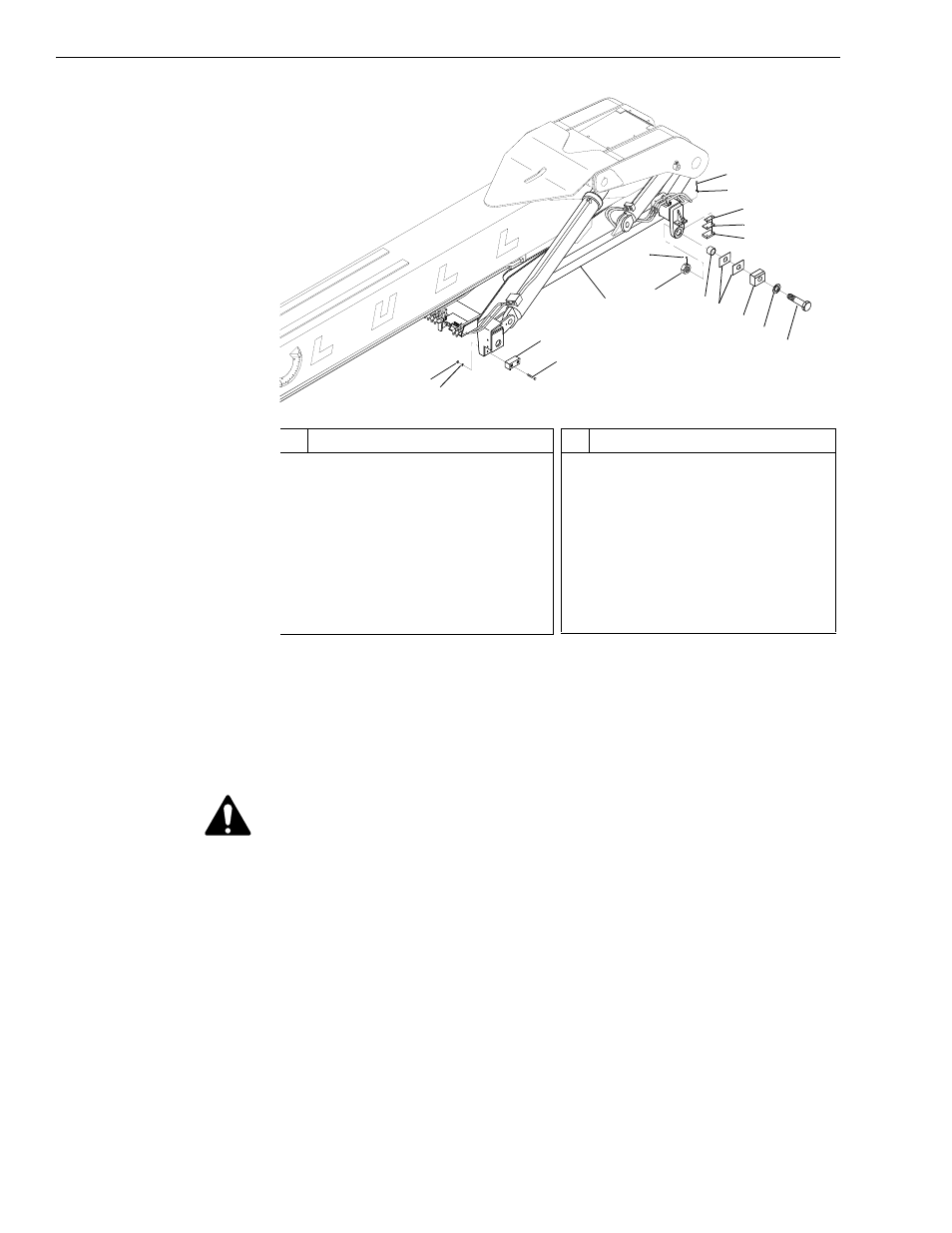
Fig. 6-250: Boom Cradle with Boom Installation
9. (Ref. Fig. 6-250) The following steps are necessary if the boom and
boom cradle are to be removed as an assembly.
a. Use sling(s), crane, or other suitable means to support the boom
and boom cradle assembly.
WARNING: To avoid personal and/or equipment damage, supporting the
boom and boom cradle is essential before removing any
additional mounting hardware. Use suitable blocking and
lifting devices when removing heavy machine components.
b. Remove the four (4) each nuts (Item 1) and lockwashers (Item 2)
securing the two (2) front slide blocks (Item 4) to the boom cradle
(Item 5). Remove the four (4) capscrews (Item 3) and the slide
blocks.
c. Remove two (2) rear support block assemblies (Items 13 thru 17)
as described in Step 3 and Step 4 under “Rear Spacer Blocks,
Support Blocks, and Shims” on page 6-242.
d. Remove two (2) spacer block assemblies (Items 6 thru 12) as
described in Step 5 thru Step 7 under “Rear Spacer Blocks,
Support Blocks, and Shims” on page 6-242.
0
80
60
40
20
-20
J
1168
1
#
Description
1
Nut
2
Lockwasher
3
Capscrew
4
Front Slide Block
5
Boom Cradle
6
Setscrew
7
Spindle Nut
8
Sleeve
9
Shim
#
Description
10 Spacer Block
11 Flatwasher
12 Capscrew
13 Rear Support Block
14 Spacer (1/4" Thick)
15 Shim (22 Gauge)
16 Lockwasher
17 Capscrew
2
4
3
7
6
8
9
10
11
12
5
13
14
15
16
17