21 boom positioned below 40 – Lull 6K Service Manual User Manual
Page 523
Frame Tilt and Oscillation
Service Manual — Models 644B, 6K, 844C, 8K, 1044C, 10K
7-21
Boom Positioned Below 40°
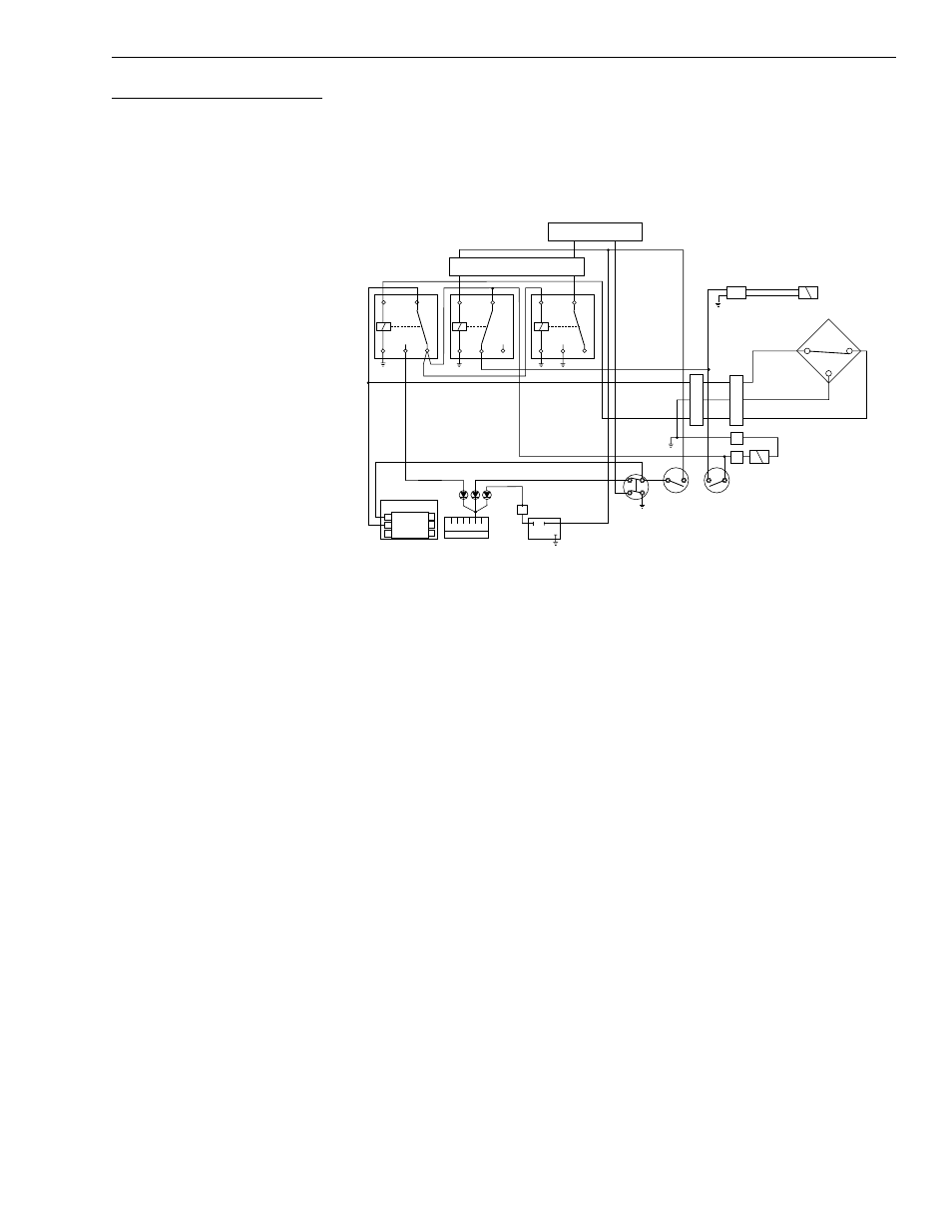
Fig. 7-14: Circuit Operation Below 40°
(Ref. Fig. 7-14) The following describes the rear axle stabilizer circuit logic
when the boom is positioned below 40° elevation.
1. When the boom is below 40°, the proximity switch (S1) is sensing the
outer boom. Therefore, the proximity switch closes. See “Boom
Elevation Proximity Switch” on page 7-43 for more information.
2. A closed proximity switch energizes the proximity switch relay (R1).
Power is routed through relay (R2) and onto the solenoid valve (V1) on
the stabilizer block. Power is no longer routed to the transmission
(ECU).
3. With solenoid valve (V1) energized, hydraulic fluid is allowed to flow
freely to/from the rear oscillation lock cylinder. This allows the frame to
pivot on the rear axle. See “Oscillation Control Block” on page 7-31 for
more detailed information about the functions of control block
components.
4. Power is routed from relay (R1) to frame tilt lockout solenoid valve (V2).
The solenoid valve energizes and allows hydraulic pilot pressure to the
routed to the frame tilt control valve spool. The frame may then be
tilted.
J1
2
6
1
Dash Panel
ECU
R1
R2
R3
S2
S3
S1
V2
V1
B
1
C
Parking
Pressure
Brake
Switch
Fuse
Panel
Transmission
Disconnect
Switch
R1 = Proximity Switch Relay
R2 = Service Brake Relay
R3 = Oscillation Lock Warning Light Relay
S1 = Proximity Switch
S2 = Service Brake Pressure Switch
S3 = Frame Tilt Override Pressure Switch
V1 = Stabilizer Block Solenoid Valve
V2 = Frame Tilt Lockout Solenoid Valve
B
A
C
B
A
2
3
6
5
4
A B C D E F
D
2
3
7
+
+
–
–
A
B
C
Solenoid
Valve On
Stabilizer
Block
A
B
6 Pole
W/P
Conn.