R4 r5, Top view - valve plate – Lull 6K Service Manual User Manual
Page 117
Reference Diagrams
Service Manual — Models 644B, 6K, 844C, 8K, 1044C, 10K
4-30
B
A
IN
OU
T
CARR
AUX
TRANS
FRAME
B
A
PB
A
1
B
1
P2
P1
B3
A3
HOIST
TELESCOPE
IN
A
IN
B
OUT
ENGINE
WATER
TEMPERATURE
ENGINE
PRESSURE
OIL
VOLTAGE
BATTERY
FUEL
LOCK
OSC
REAR
BRAKE
PARK
PRESS
BRAKE
LOW
10
11
12
7
9
8
1
4
5
6
8
5
GRD
1
12
OIL
2
11
LAMPS
3
10
POWER
4
9
WATER
6
7
FUEL
1
7-1/2A
3
2
4
6
5
20A
10A
10A
30A
10A
86
30
85
87A
87
85
87A
87
86
30
RUMENT PANEL
NG BRAKE VALVE
LC
PD
STP
PLT
PR
PU
P1G
STB
OR2
PF
BOOM/
TRANSFER
EXTEND
LOCK
TOP VIEW - VALVE PLATE
ER - BASE END
L PRESSURE SWITCH
PSI DIFFERENTIAL
92 PSI DIFFERENTIAL
R4
R5
S4
SWITCHED
(36445A)
FUSE PANEL
BOOM EXTEND PORT
BOOM / TRANSFER EXTEND
LOCKOUT VALVE (38655A)
TE
BE
T
TRANSFER
EXTEND PORT
POWER
- PROXIMITY SWITCH
RELAY - BOOM EXTEND
IN
BOOM EXTEND
PROXIMITY SWITCH
CLOSED WHEN
SENSING METAL
GROUND
OUT
POWER
12 VDC
(38137A)
(P30796)
(P30796)
- BOOM EXTEND WARNING
LIGHT RELAY
SOLENOID
C
A
BROWN
BLACK
YELLOW - 16
YEL - 16
WHITE - 16
RED - 16
WHITE - 16
RED - 16
RED -
1
6
RED -
1
6
TAN - 16
TRANSFER
LOCKOUT
SOLENOID
OOM EXT.
XT. ALLOWED
- BOOM EXT.
XT. DISABLED
BOOM EXTEND
WARNING
LIGHT (#9)
OFF
ON
OFF
OFF
XT. ALLOWED
OOM EXT.
OOM EXT.
XT. ALLOWED
- BOOM EXT.
XT. DISABLED
ON
- BOOM EXT.
XT. DISABLED
ON
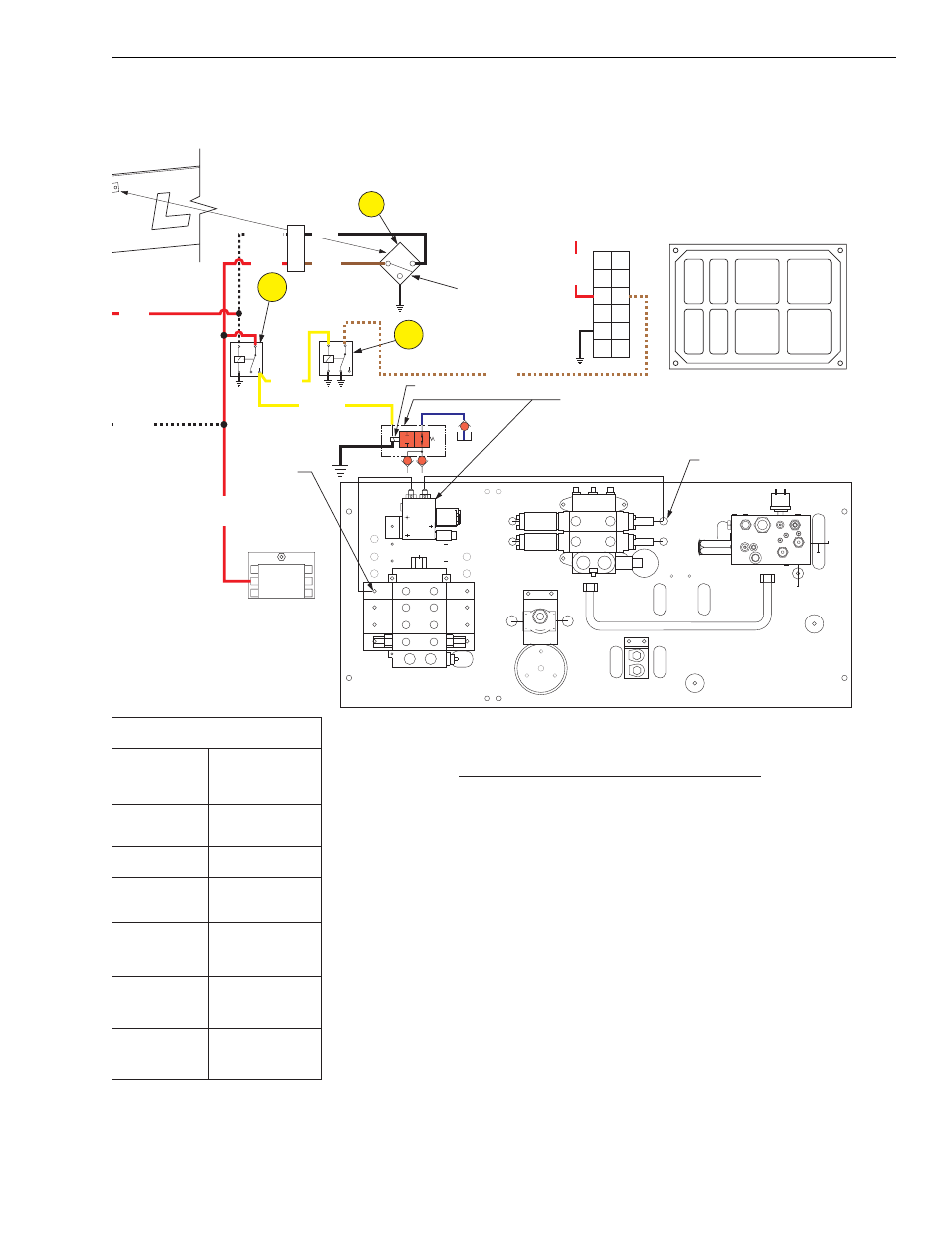
BOOM/TRANSFER EXTEND LOCKOUT CIRCUIT
The boom extend / lockout circuit is designed to increase
stability of the machine by limiting how far the boom can be
extended with the outriggers up. The system will disable the
boom extend and transfer extend functions at a boom extension
of 21 feet and turns on warning light #9 on the cluster gauge.
The left and right outriggers must be lowered to the ground to
allow the boom or transfer carriage to be extended further.
Normally open differential pressure switches in the outrigger
cylinders close when the base end pressure exceeds the rod
end pressure by 92 PSI. When both pressure switches close,
this completes the circuit allowing the boom and transfer
carriage to be extended and turns off light #9. The system is fail-
safe because it requires an electrical signal to enable the boom
to be extended beyond 21 feet.
Boom/Transfer Extend Lockout Circuit Operation, Control Manifold Hydraulic System - Diagram 8