Lull 6K Service Manual User Manual
Page 217
Supply, Pressure, and Return Hydraulics
Service Manual — Models 644B, 6K, 844C, 8K, 1044C, 10K
5-73
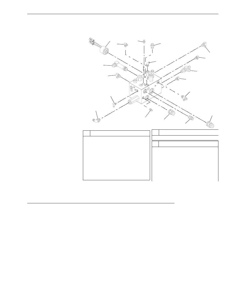
5. Inspect and replace any damaged fittings or O-rings. Lubricate each
O-ring with hydraulic oil before installing it on fitting or low brake
pressure switch.
Fig. 5-44: Hydraulic Control Manifold Block Fittings Removal/Installation
Inspection and Cleaning, Hydraulic Control Manifold Plugs and Cartridge Valves
(Ref. Fig. 5-45) The following procedure describes disassembly and
cleaning of the hydraulic control manifold plugs and cartridge valves.
1. Tag and remove seven (7) valve cartridges (Items 1, 7, 11, 15, 21, 25,
and 29).
2. Remove eighteen (18) O-ring plugs (Items 10, 19, and 34) and two (2)
orifice plugs (Item 20).
3. Thoroughly flush hydraulic control manifold block (Item 33) with
solvent. Dry with compressed air.
4. Clean O-ring plugs and orifice plugs with solvent. Dry with compressed
air.
5. Remove and discard all cartridge O-rings.
K
1062
1
3
4
5
6
7
8
9
10
11
12
13
14
15
16
17
18
#
Description
1
Low Brake Pressure Switch - SW
Port
2
O-Ring Elbow - P1G Port
3
O-Ring Connector - STP Port
4
O-Ring Connector - STB Port
5
O-Ring Elbow - PLT Port
6
O-Ring Elbow - B Port
7
O-Ring Elbow - ACG Port
8
O-Ring Tee - F Port
9
O-Ring Elbow - PG Port
#
Description
10 O-Ring Tee - T Port
11 O-Ring Connector - EF Port
12 O-Ring Connector - CF Port
13 O-Ring Connector - P1 Port
14 O-Ring Connector - LS Port
15 O-Ring Elbow - ST Port
16 O-Ring Elbow - PSG Port
#
Description
2