Lull 6K Service Manual User Manual
Page 222
Supply, Pressure, and Return Hydraulics
5-78
Service Manual — Models 644B, 6K, 844C, 8K, 1044C, 10K
Removal
Pump Unloader Valve
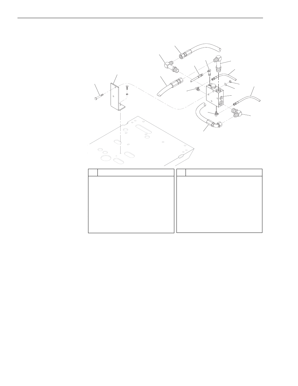
Fig. 5-47: Pump Unloader Valve Installation - Control Manifold Hydraulics
(Ref. Fig. 5-47) The following procedure describes removal of the pump
unloader valve.
1. Follow preparation procedures as outlined in Section 3 of this manual.
Be sure to follow the guidelines in this section detailed under “General
Hydraulic Maintenance Practices” on page 5-4.
2. Install brake pressure diagnostic port test gauge into brake diagnostic
port (see page 5-90).
3. While watching test gauge, press brake pedal numerous times until
pressure gauge reads 0 psi. Remove test gauge from diagnostic port.
4. For 644B, 844C, and 1044C models, refer to roll-back hose tray
removal procedures on page 5-94.
5. To avoid contamination of the system, clean pump unloader valve.
K
1112
#
Description
1
Capscrew
2
Mounting Bracket
3
Hydraulic Hose
4
Elbow
5
Hydraulic Hose
6
Elbow
7
Hydraulic Hose
8
Elbow
9
Elbow
#
Description
10 Hydraulic Hose
11 Nut
12 Lockwasher
13 Pump Unloader Valve
14 Hydraulic Hose
15 Elbow
16 Elbow
17 Hydraulic Hose
2
1
3
4
5
6
17
15
16
11
12
14
10
9
7
8
13