Reference diagrams, Mid-inlet control valve – Lull 6K Service Manual User Manual
Page 102
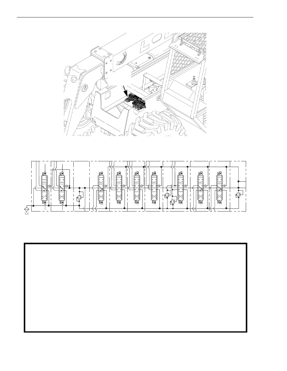
Reference Diagrams
4-15
Service Manual — Models 644B, 6K, 844C, 8K, 1044C, 10K
3175
PSI
L.H.
OUTRIGGER
R.H.
OUTRIGGER
FRAME
TILT
TRANSFER
CARRIAGE
TILT
AUX. 1
A
A
A
A
A
A
B
B
B
B
B
B
2800
PSI
A3
A4
B4
B3
BOOM HOIST
TELESCOPE
A
A
B
BOOM
A2
B5
A5
A1
B1
A6
B6
2800
PSI
P
B2
B
A
AUX. 2
(OPTION)
3050
PSI
B
(OPTION)
(OPTION)
Mid-Inlet
Control
Valve
This diagram applies to the following Model(s) and serial numbers:
644B-37 ....... S/N: 591, 667-
644B-42 ....... S/N: 208-
844C-42 ....... S/N: 622-
1044C-42 ...... S/N: 117-
Schematic, Models 644B, 844C, 1044C-42 w/Turbocharged Engine, Mid-Inlet Hydraulic Sys.-Diagram 4
This manual is related to the following products: